
Summary of 10 steps to selecting a microcontroller
Selecting the right microcontroller requires a structured approach to balance technical features with business constraints like cost and lead times. Engineers must first define high-level system requirements, including block diagrams and flowcharts, before choosing a chip. The process involves identifying necessary hardware interfaces, such as communication protocols (USB, I2C, SPI) and digital/analog inputs, which determine pin counts and program space needs. Following ten specific steps ensures a rational selection that aligns with project goals.
Parts used in Microcontroller Selection:
- Hardware block diagram
- Flowchart
- Communication interfaces (USB, I2C, SPI, UART, Ethernet)
- Digital inputs and outputs
- Analog to digital inputs
- PWM modules
Selecting the right microcontroller for a product can be a daunting task. Not only are there a number of technical features to consider, there are also business case issues such as cost and lead-times that can cripple a project. At the start of a project there is a great temptation to jump in and start selecting a microcontroller before the details of the system has been hashed out. This is of course a bad idea. Before any thought is given to the microcontroller, the hardware and software engineers should work out the high levels of the system, block diagram and flowchart them and only then is there enough information to start making a rational decision on microcontroller selection. When that point is reached, there are 10 easy steps that can be followed to ensure that the right choice is made.
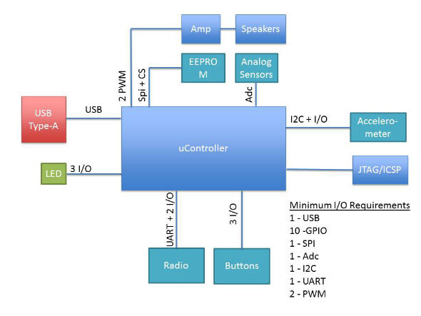
Step 1: Make a list of required hardware interfaces
Using the general hardware block diagram, make a list of all the external interfaces that the microcontroller will need to support. There are two general types of interfaces that need to be listed. The first are communication interfaces. These are peripherals such as USB, I2C, SPI, UART, and so on. Make a special note if the application requires USB or some form of Ethernet. These interfaces greatly affect how much program space the microcontroller will need to support. The second type of interface is digital inputs and outputs, analog to digital inputs, PWM’s, etc. These two interface types will dictate the number of pins that will be required by the microcontroller. Figure 1 shows a generic example of a block diagram with the i/o requirements listed.
For more detail: 10 steps to selecting a microcontroller
- Why should engineers avoid selecting a microcontroller immediately?
Starting too early is bad because the system details have not been hashed out yet. - What must be done before thinking about the microcontroller?
Engineers must work out the high levels of the system, create block diagrams, and flowchart them. - What are the two general types of interfaces listed in Step 1?
The two types are communication interfaces and digital inputs/outputs with analog to digital inputs. - Which interfaces greatly affect how much program space is needed?
Interfaces such as USB or Ethernet greatly affect the required program space. - How do interface types dictate the number of pins?
Communication interfaces and digital/analog inputs dictate the total number of pins required by the microcontroller. - What happens if you jump in before the system details are clear?
You risk making an irrational decision on microcontroller selection due to missing information. - Are there business case issues to consider during selection?
Yes, issues such as cost and lead-times can cripple a project if not considered.