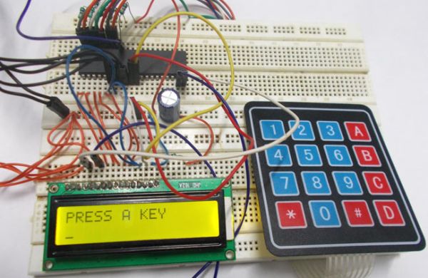
In this tutorial we are going to interface a 4×4 (16 key) keypad with ATMEGA32A microcontroller. We know that keypad is one of the most important input devices used in electronics projects. Keypad is one of the easiest ways to give commands or instructions to an electronic system.
Components Required
Hardware: ATMEGA32, power supply (5v), AVR-ISP PROGRAMMER, JHD_162ALCD (16*2LCD), 100uF capacitor, 100nF capacitor, 10KΩ resistor (8 pieces).
Software: Atmel studio 6.1 or Atmel studio 6.2, progisp or flash magic.
Circuit Diagram and Working Explanation

In circuit PORTB of ATMEGA32 is connected to data port LCD. Here one should remember to disable the JTAG communication in PORTC ot ATMEGA by changing the fuse bytes, if one wants to use the PORTC as a normal communication port. In 16×2 LCD there are 16 pins over all if there is a back light, if there is no back light there will be 14 pins. One can power or leave the back light pins. Now in the 14 pins there are 8 data pins (7-14 or D0-D7), 2 power supply pins (1&2 or VSS&VDD or gnd&+5v), 3rd pin for contrast control (VEE-controls how thick the characters should be shown), and 3 control pins (RS&RW&E).
In the circuit, you can observe that I have only took two control pins , this give the flexibility, the contrast bit and READ/WRITE are not often used so they can be shorted to ground. This puts LCD in highest contrast and read mode. We just need to control ENABLE and RS pins to send characters and data accordingly.
The connections which are done for LCD are given below:
PIN1 or VSS to ground
PIN2 or VDD or VCC to +5v power
PIN3 or VEE to ground (gives maximum contrast best for a beginner)
PIN4 or RS (Register Selection) to PD6 of uC
PIN5 or RW (Read/Write) to ground (puts LCD in read mode eases the communication for user)
PIN6 or E (Enable) to PD5 of uC
PIN7 or D0 to PB0 of uC
PIN8 or D1 to PB1 of uC
PIN9 or D2 to PB2 of uC
PIN10 or D3 to PB3 of uC
PIN11 or D4 to PB4 of uC
PIN12 or D5 to PB5 of uC
PIN13 or D6 to PB6 of uC
PIN14 or D7to PB7 of uC
In the circuit you can see that we have used 8bit communication (D0-D7) however this is not a compulsory, we can use 4bit communication (D4-D7) but with 4 bit communication program becomes a bit complex. So from mere observation of above table we are connecting 10 pins of LCD to controller in which 8 pins are data pins and 2 pins for control.
Now let’s talk about keypad, keypad is nothing but multiplexed keys. Buttons are connected in a multiplexed form for reducing the pin usage of control system.
Consider we have a 4×4 keypad, in this keypad we have 16 buttons, in normal cases we need 16 controller pins to interface 16 buttons, but this is not good in control system point of view. This pin usage can be reduced by connecting the buttons in multiplex form.
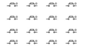
For example consider we have 16 buttons and we want to attach it to a controller to form a keypad, these keys are arranged as shown in figure:
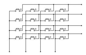
These buttons are connected by common columns as shown in figure:
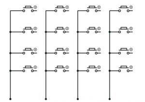
As shown in figure, non marked ends of every four buttons are dragged to gether to form a column, and so for 16 keys we have four columns.
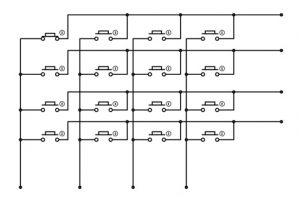
If we forget the columns connections above, and connected common marked ends of every four buttons together to form a row:
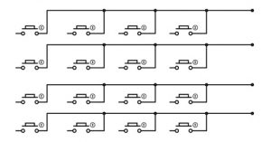
As shown in figure, for 16 keys we will have four rows as shown in figure.
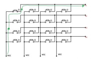
Now when they are both seen together we get something like the below circuit:
Here we have connected 16 keys in a multiplexed form so to reduce the pin usage of controller. When compared to the first case of connected 16 keys we needed 16pins on controller but now after multiplexing we need simply 8 pins of controller to connect 16 keys.
Normally this is what presented inside a keypad:
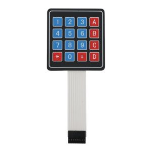
As shown in above figure there are 16 keys in the above keypad and each of these keys represent a button in the multiplexed button configuration. And also there are 8 pin connections as shown in above figure symbolizing multiplexed connection.
Now for working:
The keypad here has four columns and four rows, for identification of button pressed, we are going to use cross reference method. Here first we are going to either connect all columns or all rows to vcc, so if rows are connected to common vcc, we are going to take the columns as inputs to controller.
Now if button one is pressed as shown in figure:
After that a current flows through the circuit as shown in below figure:
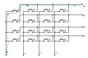
So we have C1 high, for a button press. At this very moment, we are going to shift the power and input ports that is, we are going to power the columns and take rows as inputs,
By that, there will be a power flow as shown in below figure:
So for the row we have R1 high.
As of now we have C1 high in first case and R1 high in second case, so we have matrix position of the button hence the number “one”.
If the second button is pressed, we will have C1 as column but the high logic we get in common column will be ‘R2’. So we will have C1 and R2, hence we will have matrix position of second button.
This is how we are going to write the program, we are going to connect eight pins of keypad to eight pins of controller. And for start we power four pins of controller for powering four rows of keypad, at this time the other four pins are taken as inputs. When the button is pressed corresponding column pin pulled up and so the controller pin gets pulled up, this will be recognized to change the input to power and power to input, so we will have rows as inputs.
By this we get the button pressed by the user. This matrix addresses is directed to corresponding number, and this number is shown on LCD.
Working of keypad interfacing with avr microcontroller is explained step by step in C code given below. You can also check: keypad interfacing with 8051 microcontroller.
Code
#include <avr/io.h>
//header to enable data flow control over pins
#define F_CPU 1000000
//telling controller crystal frequency attached
#include <util/delay.h>
//header to enable delay function in program
#define E 5
//giving name “enable” to 5th pin of PORTD, since it Is connected to LCD enable pin
#define RS 6
//giving name “registerselection” to 6th pin of PORTD, since is connected to LCD RS pin
void send_a_command(unsigned char command);
void send_a_character(unsigned char character);
void send_a_string(char *string_of_characters);
int main(void)
{
DDRB = 0xFF;
//putting portB and portD as output pins
DDRD = 0xFF;
_delay_ms(50);//giving delay of 50ms
int key=0;//allocating integer to reset the LCD once it reaches its display limit
int keypressed=0;//integer for storing matrix value
send_a_command(0x01); //Clear Screen 0x01 = 00000001
_delay_ms(50);
send_a_command(0x38);//telling lcd we are using 8bit command /data mode
_delay_ms(50);
send_a_command(0b00001111);//LCD SCREEN ON and courser blinking
send_a_string(“PRESS A KEY”);//displaying a string
send_a_command(0x80 + 0x40 +0);// moving courser to second line of LCD
DDRA=0xF0;//taking column pins as input and row pins as output
_delay_ms(1);
PORTA=0x0F;// powering the row ins
_delay_ms(1);
while(1)
{
if (PINA!=0b11110000)//in any of column pins goes high execute the loop
{
_delay_ms(5);
keypressed = PINA;//taking the column value into integer
DDRA ^=0b11111111;//making rows as inputs and columns as ouput
_delay_ms(1);
PORTA ^= 0b11111111;//powering columns
_delay_ms(1);
keypressed |=PINA;taking row value and OR ing it to column value
if (keypressed==0b00010001)
{
send_a_string(“1”);//if row1 and column1 is high show “1”
key++;
}
if (keypressed==0b00010010)
{
send_a_string(“4”);// if row1 and column2 is high show “4”
key++;
}
if (keypressed==0b00010100)
{
send_a_string(“7”);// if row1 and column3 is high show “7”
key++;
}
if (keypressed==0b00011000)
{
send_a_string(“*”);//if row1 and column4 is high show “*”
key++;
}
if (keypressed==0b00100001)
{
send_a_string(“2”);// if row2 and column1 is high show “2”
key++;
}
if (keypressed==0b00100010)
{
send_a_string(“5”);// if row2 and column2 is high show “5”
key++;
}
if (keypressed==0b00100100)
{
send_a_string(“8”);// if row2 and column3 is high show “8”
key++;
}
if (keypressed==0b00101000)
{
send_a_string(“0”);// if row2 and column4 is high show “0”
key++;
}
if (keypressed==0b01000001)
{
send_a_string(“3”);
key++;
}
if (keypressed==0b01000010)
{
send_a_string(“6”);
key++;
}
if (keypressed==0b01000100)
{
send_a_string(“9”);
key++;
}
if (keypressed==0b01001000)
{
send_a_string(“#”);
key++;
}
if (keypressed==0b10000001)
{
send_a_string(“A”);
key++;
}
if (keypressed==0b10000010)
{
send_a_string(“B”);
key++;
}
if (keypressed==0b10000100)
{
send_a_string(“C”);
key++;
}
if (keypressed==0b10001000)
{
send_a_string(“D”);
key++;
}
keypressed=0;//after showing integer erasing the row column memory
DDRA ^=0b11111111;//shifting input and power port
_delay_ms(1);
PORTA ^= 0b11111111;//powering row pins of keypad
_delay_ms(220);
}
if (key==16)//if 16 characters are shown on LCD
{
send_a_command(0x01);//clear lcd
send_a_string(“PRESS A KEY”);//display string
send_a_command(0x80 + 0x40 +0);//move courser to second line.
key=0;
}
}
}
void send_a_command(unsigned char command)
{
PORTA = command;
PORTD &= ~ (1<<RS); //putting 0 in RS to tell lcd we are sending command
PORTD |= 1<<E; //telling lcd to receive command /data at the port
_delay_ms(50);
PORTD &= ~1<<E;//telling lcd we completed sending data
PORTA= 0;
}
void send_a_character(unsigned char character)
{
PORTA= character;
PORTD |= 1<<RS;//telling LCD we are sending data not commands
PORTD |= 1<<E;//telling LCD to start receiving command/data
_delay_ms(50);
PORTD &= ~1<<E;//telling lcd we completed sending data/command
PORTA = 0;
}
void send_a_string(char *string_of_characters)
{
while(*string_of_characters > 0)
{
send_a_character(*string_of_characters++);
}
}
Video
For more detail: 4×4 Keypad Interfacing with ATmega32 Microcontroller