In this session we are going to design an 8×8 LED display with 8×8 LED matrix and ATmega8 microcontroller, which can show alphabets or names.
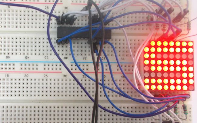
A 8×8 LED matrix contains 64 LED (Light Emitting Diodes) which are arranged in the form of a matrix, hence the name LED matrix. These matrixes can be made by circuiting 64 LEDs; however that process is time consuming. Now a day they are available in compact forms as shown in figure. These compact modules are available in different sizes and many colors. One can choose them on convenience.
The cost of module is same as cost of 64 LED, so for a hobbyist this is easiest to work on. The PIN configuration of the module is as shown in figure. The PINs should be number exactly as shown in picture for avoiding errors. We will discuss the internal circuit configuration of module in detail in description.
Components
Hardware: ATMEGA8, Power supply (5v), AVR-ISP PROGRAMMER, 100 uF capacitor(connected across power supply), 1KΩ resistor(8 pieces).
Software: Atmel studio 6.1, progisp or flash magic.
Circuit Diagram and Working
The connections which are done between ATMEGA8 and LED matrix module is shown in below figure.
PORTD, PIN0 ——————PIN13 of LED module
PORTD, PIN1 ——————PIN03 of LED module
PORTD, PIN2 ——————PIN04 of LED module
PORTD, PIN3 ——————PIN10 of LED module
PORTD, PIN4 ——————PIN06 of LED module
PORTD, PIN5 ——————PIN11 of LED module
PORTD, PIN6 ——————PIN15 of LED module
PORTD, PIN7 ——————PIN16 of LED module
PORTB, PIN0 ——————PIN09 of LED module
PORTB, PIN1 ——————PIN14 of LED module
PORTB, PIN2 ——————PIN08 of LED module
PORTB, PIN3 ——————PIN12 of LED module
PORTC, PIN0 ——————PIN01 of LED module
PORTC, PIN1 ——————PIN07 of LED module
PORTC, PIN2 ——————PIN02 of LED module
PORTC, PIN3 ——————PIN05of LED module
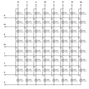
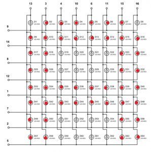
The circuit diagram of 8×8 LED matrix display is shown in below figure.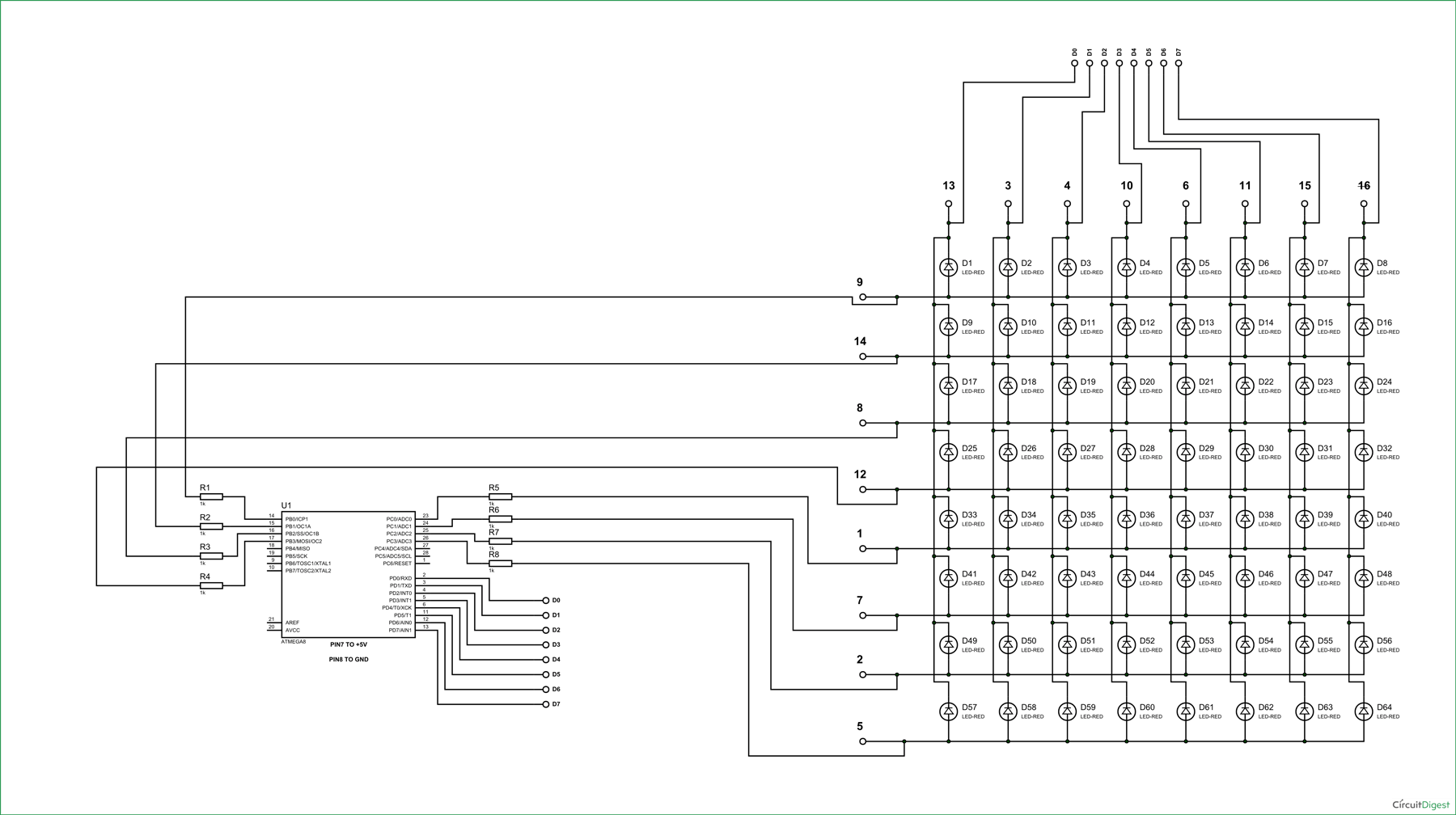
There are 64 LED arranged in a matrix form. So we have 8 columns and 8 rows as shown in figure. Over those rows and columns, all the positive terminals in a row are brought together. For each row, there is one common positive terminal for all 8 LED in that row. It is shown in below figure,
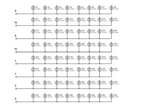
So for 8 rows we have 8 common positive terminals, consider the first row. As seen by picture, the LEDs from D1 to D8 have a common positive terminal and is brought out of LED MODULE as PIN9.
It should be seen that all the common positives of rows are not brought out of LED MODULE in orderly fashion. There is very irregularity on common terminals in every case. One should keep this in mind while connecting the terminal.
Say if we want any one or all LEDs in the first ROW of matrix to be ON, then we should power the PIN9 of LED MATRIX MODULE not PIN0.
Say if we want any one or all LEDs in the third ROW of matrix to be ON, then we should power the PIN8 of LED MATRIX MODULE not PIN2.
So whenever we want one or all LEDs in a ROW to be ON, The corresponding pin of LED MODULE to be powered.
This is not over yet by just leaving the power ROWS yields nothing. We need to ground the other end. We will discuss it below.
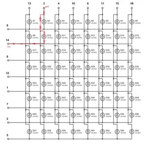
Now for this instance we ignore the common positive rows and focus on common negative columns.
So in that module all the negative terminals of first column are brought together to the PIN13. This is shown in below figure.
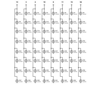
Here also there is irregularity in PIN OUTAGE of module. The first column LEDs common negative is brought out at PIN13. The second column LEDs common negative is brought out at PIN3.
One should pay attention to the pins while connecting. Now if any one or all the LEDS in first column are to be grounded, PIN13 of MATRIX MODULE to be grounded. This way goes all to the other seven common negative columns. When both the cases are put together we come across a circuit as shown in below,
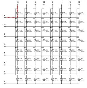
The circuit above is the complete internal diagram of LED MODULE. Say if we want to turn on LED D10 in the matrix, we need to power the PIN14 of module and ground the PIN3 on module. With this the D10 will turn ON. This is shown in the figure below. This should be first check for MATRIX to know everything in order.
Say if we want to turn on D1, we need to power PIN9 of matrix and ground the PIN13. With that LED D1 will glow. The current direction for this case is shown in below figure.
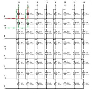
Now for the tricky part, consider we want to turn on both D1 and D10 at a time. So we power both PIN9, PIN14 and ground both PIN13, PIN3. With that we will have D2 and D9 ON along with D1 and D10. It’s because they share common terminals. So if we want to turn LEDs along the diagonal, we will be forced to turn ON all the LEDs along the way. This is shown in below figure.
So to eliminate this problem we will turn only one led on at a time. Say at t=0m SEC, LED D1 is tuned ON. At t = 1m SEC, LED D1 is tuned OFF and LED D2 is turned ON. Again at t=2 m SEC, LED D2 is turned OFF and LED D1 is turned ON. This goes on.
Now the trick is, the human eye cannot capture a frequency more than 30 HZ. That is if a LED goes ON and OFF continuously at a rate of 30HZ or more. The eye sees the LED as continuously ON. However this is not the case. The LED will be constantly turning ON and OFF. This technique is called multiplexing.
By using multiplexing, we will turn only one row at a time, and there will be cycling around the 8 rows continuously. This visualized as a completely turned ON matrix for a naked eye.
Now say we want to display “A” on the matrix.
As told we will turn ON one row in an instant,
At t=0m SEC, PIN09 is set HIGH (other ROW pins are LOW at this time) at this time,PIN3,PIN4,PIN10,PIN6,PIN11,PIN15 are grounded(other COLUMN pins are HIGH at this time)
At t=1m SEC, PIN14 is set HIGH (other ROW pins are LOW at this time )at this time, PIN13,PIN3,PIN4,PIN10,PIN6,PIN11,PIN15,PIN16 are grounded(other COLUMN pins are HIGH at this time)
At t=2m SEC, PIN08 is set HIGH (other ROW pins are LOW at this time )at this time, PIN13,PIN3,PIN15,PIN16 are grounded(other COLUMN pins are HIGH at this time)
At t=3m SEC, PIN12 is set HIGH (other ROW pins are LOW at this time )at this time, PIN13,PIN3,PIN15,PIN16 are grounded(other COLUMN pins are HIGH at this time)
At t=4m SEC, PIN01 is set HIGH (other ROW pins are LOW at this time )at this time, PIN13,PIN3,PIN4,PIN10,PIN6,PIN11,PIN15,PIN16 are grounded(other COLUMN pins are HIGH at this time)
At t=5m SEC, PIN07 is set HIGH (other ROW pins are LOW at this time )at this time, PIN13,PIN3,PIN4,PIN10,PIN6,PIN11,PIN15,PIN16 are grounded(other COLUMN pins are HIGH at this time)
At t=6m SEC, PIN02 is set HIGH (other ROW pins are LOW at this time )at this time, PIN13,PIN3,PIN15,PIN16 are grounded(other COLUMN pins are HIGH at this time)
At t=7m SEC, PIN05 is set HIGH (other ROW pins are LOW at this time )at this time, PIN13,PIN3,PIN15,PIN16 are grounded(other COLUMN pins are HIGH at this time)
At this speed, the display will be seen as continuously showing “A” character. It is shown in figure.
This is how all the characters are shown in display. After connecting circuit in proper way , as shown in the circuit diagram. We can directly give the controller instructions to perform the multiplexing in orderly fashion for the name to display. [Also check: 8×8 LED Matrix with Arduino]
Code
#include <avr/io.h>
//header to enable data flow control over pins
#define F_CPU 1000000
//telling controller crystal frequency attached
#include <util/delay.h>
//header to enable delay function in program
int main(void)
{
DDRD = 0xFF;//PORTB,C,D are set as output
DDRB = 0xFF;
DDRC = 0xFF;
char PORT[8] = {1,2,4,8,16,32,64,128};//pin values of PORTD
static int ALPHA[26][8]={{0,0b01111111,0b11111111,0b11001100,0b11001100,0b11001100,0b11111111,0b01111111},
{0,0b00111100,0b01111110,0b11011011,0b11011011,0b11011011,0b11111111,0b11111111},
{0,0b11000011,0b11000011,0b11000011,0b11000011,0b11100111,0b01111110,0b00111100},
{0,0b01111110,0b10111101,0b11000011,0b11000011,0b11000011,0b11111111,0b11111111},
{0,0b11011011,0b11011011,0b11011011,0b11011011,0b11011011,0b11111111,0b11111111},
{0,0b11011000,0b11011000,0b11011000,0b11011000,0b11011000,0b11111111,0b11111111},
{0b00011111,0b11011111,0b11011000,0b11011011,0b11011011,0b11011011,0b11111111,0b11111111},
{0,0b11111111,0b11111111,0b00011000,0b00011000,0b00011000,0b11111111,0b11111111},
{0b11000011,0b11000011,0b11000011,0b11111111,0b11111111,0b11000011,0b11000011,0b11000011},
{0b11000000,0b11000000,0b11000000,0b11111111,0b11111111,0b11000011,0b11001111,0b11001111},
{0,0b11000011,0b11100111,0b01111110,0b00111100,0b00011000,0b11111111,0b11111111},
{0b00000011,0b00000011,0b00000011,0b00000011,0b00000011,0b00000011,0b11111111,0b11111111},
{0b11111111,0b11111111,0b01100000,0b01110000,0b01110000,0b01100000,0b11111111,0b11111111},
{0b11111111,0b11111111,0b00011100,0b00111000,0b01110000,0b11100000,0b11111111,0b11111111},
{0b01111110,0b11111111,0b11000011,0b11000011,0b11000011,0b11000011,0b11111111,0b01111110},
{0,0b01110000,0b11111000,0b11001100,0b11001100,0b11001100,0b11111111,0b11111111},
{0b01111110,0b11111111,0b11001111,0b11011111,0b11011011,0b11000011,0b11111111,0b01111110},
{0b01111001,0b11111011,0b11011111,0b11011110,0b11011100,0b11011000,0b11111111,0b11111111},
{0b11001110,0b11011111,0b11011011,0b11011011,0b11011011,0b11011011,0b11111011,0b01110011},
{0b11000000,0b11000000,0b11000000,0b11111111,0b11111111,0b11000000,0b11000000,0b11000000},
{0b11111110,0b11111111,0b00000011,0b00000011,0b00000011,0b00000011,0b11111111,0b11111110},
{0b11100000,0b11111100,0b00011110,0b00000011,0b00000011,0b00011110,0b11111100,0b11100000},
{0b11111110,0b11111111,0b00000011,0b11111111,0b11111111,0b00000011,0b11111111,0b11111110},
{0b01000010,0b11100111,0b01111110,0b00111100,0b00111100,0b01111110,0b11100111,0b01000010},
{0b01000000,0b11100000,0b01110000,0b00111111,0b00111111,0b01110000,0b11100000,0b01000000},
{0b11000011,0b11100011,0b11110011,0b11111011,0b11011111,0b11001111,0b11000111,0b11000011}};//characters a,b,c,d,e,f,g,…z binary codecs
char NAME[]={2,8,17,2,20,8,19,3,8,6,4,18,19};///circuitdigest character values
uint8_t l =0;
while(1)
{
for (int m=0;m<sizeof NAME;m++)
{
l = NAME[m];
for (int n=0;n<200;n++)//execute 200 times for the eye to catch
{
for (int j=0;j<4;j++)
{
PORTB = PORT[j];// ROW
PORTD = ~ALPHA[l][j];//show half of character (COLUMN)
_delay_us(500);
}
PORTB=0x00;//clear screen after show
for (int k=0;k<4;k++)
{
PORTC = PORT[k];// ROW
PORTD = ~ALPHA[l][k+4];//show other half of character(COLUMN)
_delay_us(500);
}
PORTC=0x00;//clear screen after show.
}
}
_delay_ms(220);
_delay_ms(220);
_delay_ms(220);
_delay_ms(220);
_delay_ms(220);
}
}
Video
For more detail: 8×8 LED Matrix Interfacing with AVR Microcontroller