How you can make a simple RPM Meter using AVR ATmega8. The RPM meter we will be making is a contact less type, i.e. it measures the RPM of a rotating object without actually making any contact with it. An IR reflectance sensor will be used to sense the speed. You have to attach a white reflective object (like a white paper sticker) at one point in the periphery of rotation . Then you need to place the reflectance sensor such that the white reflector comes just above it once per rotation. In this way the sensor will give one falling edge to the MCU per rotation, we will measure number of such pulse in one second to get the revolution per second, multiplying this with 60 we get RPM.
For this project I will use a ATmega8 MCU connected to a 16×2 LCD Module for showing the RPM.
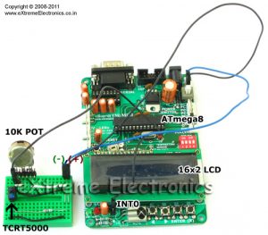
Design of AVR based RPM Meter.
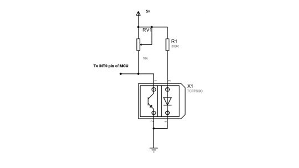
The sensor part is made up of TCRT5000 IR Reflectance sensor. It it wired as shown below. The sensor will give a LOW output whenever it detects a white reflective surface just above it. This output is feed to the INT0 pin of MCU. INT0 is a general purpose external interrupt source. It can be adjusted to interrupt the CPU on Rising, falling, low level or high level. In this project we configure it to interrupt on falling edge. When ever a falling edge (high to low transition) is detected on INT0 pin the CPU jumps to the ISR which handles the even. The ISR just increments a global variable count, in this way we keep track of number of revolution.
TIMER1, which is a 16 bit counter is used to generate an interrupt each second. On TIMER1 ISR we just copy the value of count to another global variable rps. And clear count to zero. The input to TIMER1 is taken by prescaler which is set at 1:1024, that means TIMER1 is clocked at 1/1024 of system clock. As our system clock is 1000000, timer frequency is 1000000/1024=976 Hz. To get exact 1 sec time base we use the comparator unit of timer, we set compare value to 976. So as soon as TIMER1 reaches 976 it is cleared to 0 (CTC mode) and an interrupt called output compare 1A (1 because it is timer1 and A because timer1 has 2 comparator A and B)
In the main loop of the program we just print RPM and RPS.
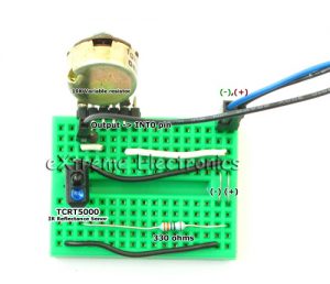
The above circuit made on a mini bread board.
Schematic of AVR based RPM Meter

AVR GCC code for RPM Meter.
#include <avr/io.h>
#include <avr/interrupt.h>

#include <util/delay.h>

#include "lcd.h"

volatile uint16_t count=0;    //Main revolution counter

volatile uint16_t rpm=0;   //Revolution per minute

volatile uint16_t rps=0;   //Revolution per second


void Wait()
{
   uint8_t i;
   for(i=0;i<2;i++)
   {
      _delay_loop_2(0);
   }
}


void main()
{
   LCDInit(LS_NONE);

   LCDWriteString("RPM Meter");
   LCDWriteStringXY(0,1,"- by avinash");

   Wait();
   Wait();
   Wait();
   Wait();

   //Init INT0
   MCUCR|=(1<<ISC01);   //Falling edge on INT0 triggers interrupt.

   GICR|=(1<<INT0);  //Enable INT0 interrupt

   //Timer1 is used as 1 sec time base
   //Timer Clock = 1/1024 of sys clock
   //Mode = CTC (Clear Timer On Compare)
   TCCR1B|=((1<<WGM12)|(1<<CS12)|(1<<CS10));

   //Compare value=976

   OCR1A=976;

   TIMSK|=(1<<OCIE1A);  //Output compare 1A interrupt enable

   //Enable interrupts globaly
   sei();

   //LED Port as output
   DDRB|=(1<<PB1);


   LCDClear();

   LCDWriteStringXY(0,0,"RPM =");
   LCDWriteStringXY(0,1,"RPS =");

   while(1)
   {
      LCDWriteIntXY(6,0,rpm,5);
      LCDWriteIntXY(6,1,rps,5);

      if(PIND & (1<<PD2))
      {
         PORTB|=(1<<PB1);
      }
      else

      {
         PORTB&=(~(1<<PB1));
      }

      Wait();
   }

}

ISR(INT0_vect)
{
   //CPU Jumps here automatically when INT0 pin detect a falling edge
   count++;
}

ISR(TIMER1_COMPA_vect)
{
   //CPU Jumps here every 1 sec exactly!
   rps=count;
   rpm=rps*60;
   count=0;
}
The above code can be compiled using avr-gcc (WinAVR distro) and AVR Studio. Details about downloading, installing and using the software is described in the following tutorial.
The code depends on the LCD Library for displaying textual/numeric data on a standard 16×2 LCD Module. The file “lcd.c” must be copied to the project folder and added to the project using AVR Studio. See LCD Tutorial for more info. Compatible lcd.c and lcd.h files are provided at the bottom of this article.
After compiling the code, burn it to the MCU using an AVR Programmer. The Fuse bits must be set as follows.
- HIGH=D9
- LOW=E1
Please note that the above is default for ATmega8, so if you purchased a new chip then you do not need to change them. But if you have purchased xBoard MINI v2.0 then you need to write the above fuse bytes, as xBoard MINI v2.0 used different configuration.
Testing the RPM meter.
After powering on the system adjust variable resistor RV1 until the LCD start showing up some text. Then bring the reflective surface above the sensor and adjust RV2 until LED D1 start glowing. Once LED start glowing move the reflective surface away from the sensor, the LED should turn off. Now the system is ready to measure the RPM.
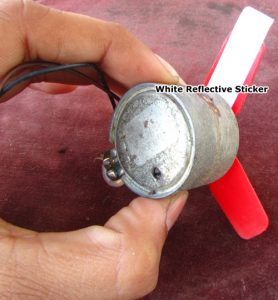
I have used a small 12v motor to test, I have attached a small fan onto the motor.
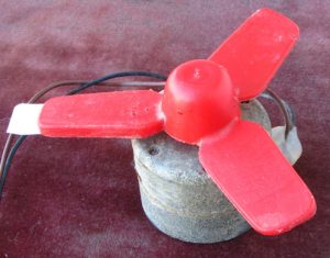
One of the blade of the Fan has a white paper sticker.
I have use xBoard MINI v2.0 as the development board. So I don’t have to wire up the entire circuit. The power supply, LCD and MCU core (and much more) are pre-built.
Downloads
- Complete AVR Studio Project (With compatible LCD Lib)
- HEX File ready to burn.
Help Us!
We try to publish beginner friendly tutorials for latest subjects in embedded system as fast as we can. If you like these tutorials and they have helped you solve problems, please help us in return. You can donate any amount as you like securely using a Credit or Debit Card or Paypal.
Source: ATmega8 based RPM Meter