Introduction.
Nowadays, USB is the most popular connection between PC and peripherals such as AVR programmers, printers, scanners etc. For that reason I had to modify my old serial AVR In-System-Programmer (ISP) to work with USB connection. You can say, “use a USB to Serial adaptor to connect your AVR ISP with your PC”. Yes, that could be a solution but it would cost me more money than a singe FT232BM chip because I had to include an USB to RS232 adaptor and a power supply for my programmer. (almost €30).
So, the solution was to replace the two transistors, that were used to adapt the RS-232 voltage levels to TTL voltage levels, with a USB to RS-232 chip such as FT-232BM.
Initially, I used the John Samperi’s firmware V3.2 but afterwards I found out the Klaus Leidinger’s firmware that was a little bit faster. So, I chose the second one firmware but I had to modify the source code to work with 11.0592MHz crystal instead of 7.3724MHz that was initially designed because I couldn’t find this crystal in the market .
This programmer worked perfect with AVRprog but then I found a software that could support much more AVR devices than the AVRprog could program. This software is AvrOspII V5.47.
The circuit.
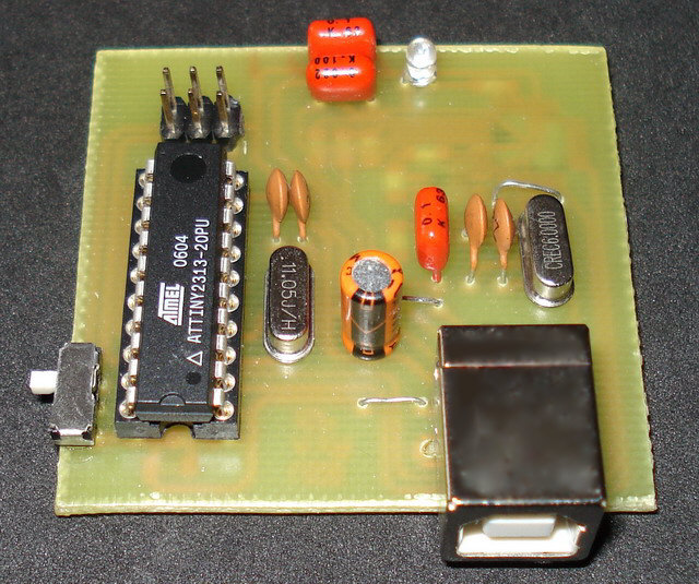
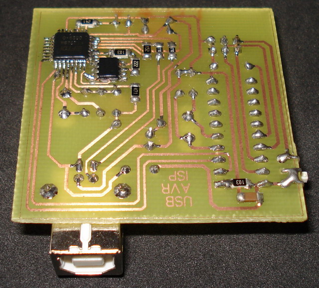
Following the schematic diagram that I read in the FT232BM manual I made the connections between ATtiny2313 and FT232BM. The FT232BM requires a few and ordinary components to work. When you connect this circuit to your PC you will see the message ” a new hardware was found” and then the factory name of FT232BM. IC1 is a serial EEPROM that used to store user’s settings. So, you can rename this programmer to be appeared as “AVR In-System-Programmer” or “MyAVR programmer”. Furthermore, you can add the firmware version of your circuit. Of cource, you can bypass this component because it’s optional. I saw that the programmer works with or without this EEPROM. Anyway, FTDI suggests you to use this EEPROM. Led D1 flashes when data are transmitted or received by FT232BM. CN1 is a USB-B connector and CN2 is a 6-pin connector to your target AVR (it is connected to the AVR to be programmed). The S1 switch is used to supply your target circuit with +5V from the USB connector of your PC. In this case you won’t need any additional power supply for your target circuit. Consider that a single USB port can supply up to 500mA current. You should not exceed this current limitation including the current that needs your AVR programmer too.
For more detail: USB AVR programmer using ATtiny2313 microcontroller


