Contents
hide
- 1 Khz From a Quartz Crystal
- 1 V P-P Sine Wave Calibrated Output
- 1 KHz Square Wave Output
- 900 mv Inverted Sine Wave Output (Uncalibrated)
Downloads
Download the WINAVR main source for the 2313 version of the firmware: 2313sine.c.
Download the complete zipped WINAVR project for the 2313 version of the firmware: 1_kHz_sine_2313.zip.
Also, Download the WINAVR main source for the 8515 version of the firmware: 8515sine080210B.c.
Download the complete zipped WINAVR project for the 2313 version of the firmwre: 1_KHz_sine_wave_8515.zip.
Find updates at www.projects.cappels.org.
Background
If found myself in need of a 1 KHz signal source for an experiments. My function/sweep generator was needed as a pulse generator for the same experiment, so I went though my junk box, looking for circuits from long ago that might fill the need, but found nothing useful.
I had a board with an AT90S8515 and an 8 bit resistor ladder network on it, which serves as a DAC (digital to analog converter), so I thought “This will be easy.” and sat down to write the code. Since I wrote it in C rather than assembly, writing the code took much longer than I expected, but in the end, I managed to get it to do what I wanted it to do, and I fixed the typographical errors.
The little generator with the AT90S8515 worked well enough for that experiment, that I decided to build up a version that uses the ATTINY2313 or AT90S2313 (I tested the firmware on both chips) so the 1 kHz sine wave generator would be available for some future experiments that I am planning.
At this point, you might wonder at my choice of an AT90S2313 instead of the ATTINY2313. I still have lots of AT90S2313’s and intend to use them where I can. There is not much of a market for obsolete controllers.
Code is provided for the ATTINY2313/AT90S2313 and the ATMEGA8515/AT90S8515. The ATTINY2313 hex file was tested on both the ATTINY2313 and the AT90S2312, while the AT90S8515 hex file was only tested on an AT90S8515. The AT90S8515 hex file is fully expected to run on the ATMEGA8515 without any problems, provided that the ATMEGA8515 is operated in the AT90S8515 compatibility mode (see below).
It should be a (nearly) trivial exercise to re-target the code to compile on any AVR controller with an 8 bit I/O port.
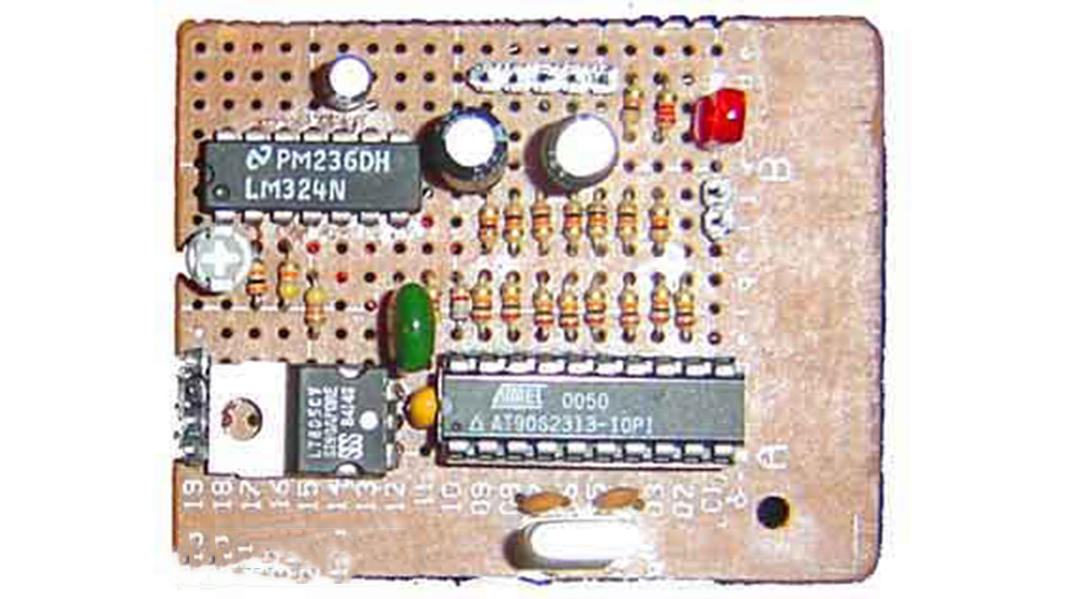
I would like to explain the new technologies developed for this circuit, but there are no new technologies involved. The firmware sends 8 bit values corresponding to 32 different values per cycle of the firmware, and this appears on an output port, to which is connected an 8 bit DAC. The output of the DAC. Since the sine wave frequency is 1 kHz, a new 8 bit value is sent to the output port every 1/32,00 seconds (every 31.25 microseconds).
The DAC is made up of 9 each 20 k Ohm and 7 each 10 k Ohm resistors, connected as an R-2R ladder network. The output of the DAC shunted by a voltage divider, whose resistance is 2.8 k Ohms, which simultaneously decreases the amplitude of the the sine wave to about 900 millivolts. Without the voltage divider (6.8k and 4.7K, the output would be nearly 5 volts peak-to-peak.) An integrated circuit DAC would have worked just fine, and I have some laying around, but somehow, it was more satisfying to make my own DAC with resistors.
Take note, that I used 5% resistors in the DAC, and if the resistors had been at the edge of their specification. The monotonicity would have been about 4 /12 bits. Fortunately, the resistors that I have bothered to measure are much closer to their specified values than this. Even more important, is that in this application, particularly when only generating a relatively coarse 32 values sine wave, a little error in monotonicity only results in as slight increase in harmonic content, and the low pass filter takes care of it.
Spurious signals in the output were about 40 db below the 1 kHz carrier in the original circuit. But a I added a capacitor to the 2313 circuit that is also in parallel with the output of the DAC forms an approximately 1.5 kHZ single pole low pass filter. Which is enough to bring the spurious signals to about 50 db below the 1 kHz sine wave. While not affecting the amplitude of the 1 kHz signal much at all.