Have you played with Arduino’s and now have a taste for microcontrollers?
Have you tried to go beyond Arduino but got stopped by the dense datasheets?
This is the instructable for you!
I was working on an instructable for the epilog contest which would wirelessly link two smoke alarms.
I wrote all the code and prototyped on a breadboard.
As the deadline drew near I built the hardware but no matter what I tried I couldn’t make it squeeze into the tiny space available.
As I wallowed in self pity, I thought of what a waste it would be for all that I learnt to be left in my head, so here it is!
This instructable will take you from the basics of bitwise manipulation to making good use of standard AVR peripherals such as timers, interrupts & serial communications.
It will also cover common extras such as Infrared remote controls, radio communications and more.
So jump in, skip what you know and brush up on what you need to.
Create the breadboard projects presented and learn new things!
Step: 1 Binary and bitwise operations
Before we dive into datasheets we need to understand some low level concepts that you will use every time you want to do anything interesting with a micro.
Lets start at the most basic, the bit.
A bit is the smallest unit of data to a computer, it is either a ‘1’ or a ‘0’.
In other words it is either on, or off.
To do anything useful in a computer though, a single bit is not enough, so they are combined into bytes.
A byte is 8 bits together, and using binary counting a byte can either store 0-255 (256 numbers) or -128 to 128.
For example:
00000000 = 0
00000001 = 1
00000010 = 2
00000011 = 3
00000100 = 4
Just like when you are counting in decimal (base 10, as in 10 fingers!), when you go past 9, you put a 1 in front and put the second digit as 0.
It is the same with binary, except as there is only 0 or 1, when you go past ‘1’ you put a 1 in front and a ‘0’ as the second digit.
The features of a microcontroller are controlled by registers. In the case of an 8-bit AVR they are either 8 or 16 bits long.
Instead of the whole thing representing a number however, each bit determines if a certain feature is on or off.
We will look at a lot of different registers later, but for now let’s make up an imaginary one so we can see how to manipulate them.
Imagine we find a register in the datasheet that connects to 8 LEDs called LEDREG.
Each bit in the register is either a 1 or a 0, the LED is either on, or it is off.
We could turn on the first LED like so:
LEDREG = 1; // 00000001
2nd LED
LEDREG = 2; //00000010
But what about the 3rd LED?
If we did this:
LEDREG = 3; //00000011
We wouldn’t get the 3rd LED, we would get LED 1 & 2 lit up instead!
With registers it isn’t the number that matters, but what the underlying bits look like.
The 3rd LED would look be like this:
LEDREG = 4; //00000100
If you wanted to turn on different patterns of LEDs you could work out all 256 combinations, but that would be tedious.
There is a better way!
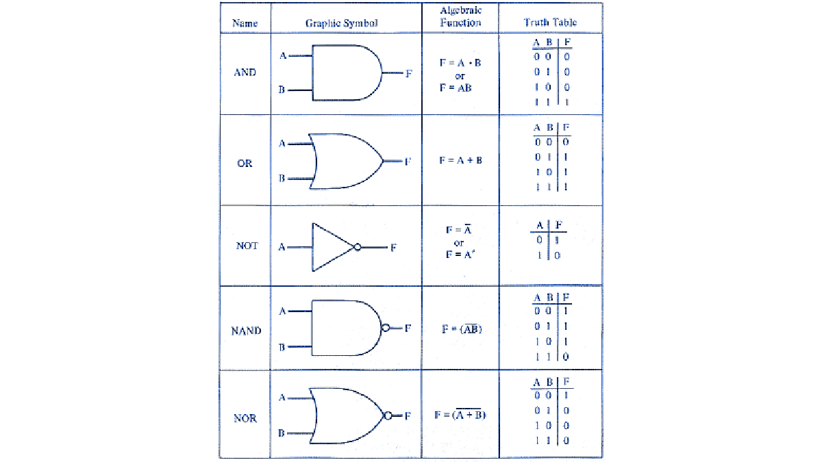
Boolean logic
Computers at the lowest level work with something called boolean logic.
They use logic gates to combine binary numbers.
For example an AND gate will only output a 1 if both inputs are 1.
An OR gate will output a 1 if either of it’s inputs are 1.
Have a look here:
http://www.electronics-tutorials.ws/boolean/bool_6.html
It shows the ‘truth tables’ for common logic gates.
So, what use is all this to us?
We can make use of these logic gates directly using bitwise operators
Bitwise operations
Lets say we already have the 3rd LED on:
LEDREG = 4; //00000100
How can we turn on the first LED?
We could put in the value of 5 (00000101) but we don’t want to have to figure out which combination each time.
Instead we can use an OR operator like so:
LEDREG = LEDREG | 1;
What this means is this
00000100 OR
00000001
————–
00000101
The OR operator lines up each bit and if it is on in either byte, it will be on in the output.
A quicker way to write “LEDREG = LEDREG | 1;” is:
LEDREG |= 1;
You can also chain your operators like so:
LEDREG |= 1 | 2;
This will come in handy when we learn shift operators.
What if you wanted to toggle all of the LEDs?
You could use a NOT operator:
LEDREG = ~LEDREG;
A NOT operator flips all the bits, so you get:
00000101 NOT
————–
11111010
Next lets look at an AND operator.
AND is used to mask a value.
That is, it is used to blank out sections of a byte but keep the value of the unmasked section, like so:
11111010 AND
00001111
————-
00001010
You can use an AND to turn off a whole group of LEDs without changing the state of the rest.
In the above example it would be used like:
LEDREG &= 15; //00001111
One more useful operator before we move on is the XOR.
XOR stands for eXclusive OR.
It is similar to an OR gate, however if both bits are on, then they are turned off.
For example:
LEDREG ^= 15;
00001010 XOR
00001111
————-
00000101
Now, by themselves the operators are limited, you still need to convert from binary to the equivalent decimal number.
This is where shift operators come in
Shift operators
A shift operator simply shifts all the digits left or right.
For example a left shift of 1:
x = 5 << 1;
gives you x == 10
in binary that is:
00000101 <<
————-
00001010
A right shift simply moves the bits to the right:
00001010 >>
————–
00000101
Any bits at the ends are simply lost (or stored in a carry register, but lets ignore that for now!)
A shift operator can be used as a very fast multiplication & division, as long as you are happy with only multiplying / dividing by powers of 2, eg:
x << 1 == x*2
x << 2 == x*4
x << 3 == x*8
Shifts are used a lot in setting registers.
Lets return to our LED example.
If we want to set the 6th bit, instead of working out what number that would be and then ORing it with the register, we can use a left shift like so:
LEDREG |= (1<<5);
NB: It is ‘5’, not ‘6’ as we only need to move the ‘1’ 5 times.
In binary it would look like so:
00000001 <<
————-
00100000
Which is then ORed with the register like so:
00000101 OR
00100000
————-
00100101
In datasheets, the position of a certain bit is usally given a name such as “RXEN” which is used to turn on receive mode in the serial peripheral and “TXEN” for transmit.
Together they would look something like this:
UCSRB |= (1<<RXEN) | (1<<TXEN);
This should be enough to get you started, lets move onto some real examples!
Step: 2 IO Pins
So, now armed with all of this bitwise knowledge, lets put it to some use!
One of the first things you will want to do with a microcontroller is to read a button and turn on an LED.
For this example I am going to use an ATtiny2313 MCU.They are cheap and come with 18 IO pins, 2K of Flash and only 128 bytes of RAM!
You should open up the datasheet to follow along: ATtiny2313 Datasheet
Start out by building the circuit on a breadboard.The MCU can use between 1.8/2.7 and 5.5v depending on the version you have.
To power the chip, I am using a 3.3v regulator, you can use a different value, however stay inside the operating values, and keep above 2v so you can easily power the LED.
Connect the regulator to a power source such as a 9v battery or a plug pack (I have one rated at 9v that actually delivers 12v!).
On the MCU connect pin 10 (GND) to the negative / gnd of your regulator and pin 20 to VCC (power).
Connect a push button between GND and pin 13 (any IO pin would do, but stick with the same so the code just works for you).
Connect the LED’s cathode (a flat spot on the LED and the shortest lead) through a resistor to ground.Connect the Anode (longest lead) to pin 12.
Now, onto the code!
If you don’t know how to put code on an AVR, there will be an appendix at the end of this instructable explaining it, go read it now and come back when you are ready.
For so little code, we have a lot of explaining to do!
DDRB is the “Data Direction Register for PortB”
This register determines if the IO pins are used just to measure voltage on the pin or if they can sink / source current.
When 0 they are high impedance and won’t supply enough current to power an LED for example, but they can be used to check if a pin is high or low.
When 1 they are low impedance and can supply or sink up to generally 20mA, enough to power an LED or a transistor (to switch bigger loads).
Here PB0 (Pin 12) is set to low impedance to drive the LED.
The next line sets the PORTB register.This register is used to set the value of a pin, as this pin (PB1 = Pin 13) is being used for a button, we are going to set it high by default.
When the button is pressed, connecting to ground, this pin will be pulled low.
Next up is our infinite loop.
This for loop will run until the power is cut!
Inside the loop we test the state of the button, it is a busy line, so lets break it down.For the if condition we have:
!(PINB & (1<<PB1))
We start with a NOT (!) which turns a true into a false and visa versa.
Next we have:
PINB & (1<<PB1)
PINB is the register you read to find out the value of the IO pins.
The “&” is being used to mask out just the value of (1<<PB1) which as we learnt earlier, is a single bit turned on in the PB5 position.
So all up we are checking if the bit at PB1 in PINB is high, and then inverting it.
So we are checking if the PB1 pin is low (the button pressed).
If it is pressed we turn the LED on:PORTB |= (1<<PB0)
This is using the OR operator and the left shift that we covered earlier, setting the pin high.If the button isn’t pressed we want to clear the pin (pull it low):
PORTB &= ~(1<<PB0)
This uses the AND operator along with the NOT and left shift to turn just that one pin off (low).
Step: 3 Datasheets

Now that you have an idea of how it all works, you need to know where to find all of the registers, their names and what they do.
This is when you turn to the datasheet.
Datasheets are where the manufacturer places all the important information from electrical ranges and tolerances to how to program and use the device.
They exist for any electronics component you could think of, but here we are just going to focus on microcontrollers, AVRs in particular.
Head to Google and do a search like so:
attiny13 datasheet
attiny2313 datasheet
etc
Look for a PDF from atmel’s site.
You should find something like these:
www.atmel.com/dyn/resources/prod_documents/doc2535.pdf
www.atmel.com/dyn/resources/prod_documents/doc2543.pdf
The first page is almost like a marketing pamphlet, telling you how much flash & ram it has etc
The next page will usually be the pin configurations, this is very handy to keep close, you might even want to print out this one page.
It lists the locations of each pin, it’s name (Port name such as PB5) and it’s alternative functions.
The IO pins can be more then just IO, some double as programming pins, others might be an analogue pin or the pins needed for a serial or SPI bus.
Any of the “INT*” or “PCINT*” pins are interrupts, which we will cover later.
From here there are some explanations of what the pins are, and links to other parts of the PDF which tell you about the alternate functions.
However the best way to proceed from here is to look at Table of contents to find the features you are interested in using.
Open the second PDF linked above (the attiny2313) and jump to the USART section.
We will cover the USART in depth later, for now lets get a feel for how the information is presented in the datasheet.
The first thing we see is the UDR register, for now lets skip over that and have a look at the UCSRA register.
The register is shown as a set of named boxes, each one represents a bit of the register.
The next line lets you know if you can read this register, write to it or read and write.
Some bits are one way only.
The third row tells you the default value that register is set to when the device powers on.
After the diagram each bit is described.
Some bits are used by the peripheral to tell your code something, and others are used by your code to change the behaviour of the peripheral.
If you scroll down to the UCSRC register you will see tables telling you the different configurations you can set based on the combinations of bits set.
The UCSZ set (UCSZ2, UCSZ1, UCSZ0) of bits are used in combination for 5 different modes and 3 reserved settings.
Reserved settings should not be used, as they will have no effect now, but in a future MCU they might mean something you won’t know about.
So to keep your code portable, don’t use reserved settings or bits.
For more detail: A complete starter guide to AVRs using attiny2313 microcontroller