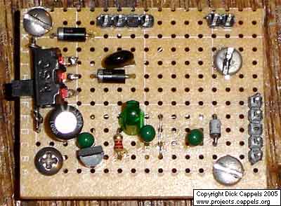
It has been said that a man with one watch knows what time it is, but a man with two watches is never sure. The same can be said for a person who has more than one voltmeter. In my situation, I have several voltmeters in each of two different locations a third of the way around the world apart. The best solution would be to send the meters to NIST traceable calibration labs, but that’s too expensive for me. Eying some of the semiconductor manufacturer’s web sites, I saw that modern-day precision semiconductor references are accurate, stable, and inexpensive, so I bought some. Here is how I hooked them up.
I went looking for a reference chip between 1 and 2 volts, so I could check the calibration of my digital voltmeters on their 2 volt scale. The Maxim MAX6168Am a 1.8 volt, 5 parts per million per degree C reference was appealing, but I was not able to find one available i small quantities for delivery soon enough for my purpose. After shopping around, I settled on the National Semiconductor LM4140-1.0 precision voltage regulator, which I was able to buy from Digikey for $3.58 each.
The National part, specifically an LM4140CCD-1.0-ND is specified to have a nominal output voltage of 1.024 volts, within 0.1% -that’s accurate to within about 1 millivolt. The temperature dependent drift is better than 10 parts per million per degree C, and the aging drift is less than 60 parts per million for the first 1,000 hours. Since the accuracy is within one digit of my best meters, it is more than adequate from my anticipated purposes.
This basic circuit should be useful for many of the other series connected voltage reference chips out there, though it might be a good idea to change the 78L05 voltage regulator to one with an ouput voltage appropriate for the particular regulator, and to similarly change the output protection zener to one with an appropriate voltage fo the particular regulator used.
A keyed power input connector, series rectifier and a shunt rectifier, both 1N4007, prevent reverse voltage from being applied to the power input. A 27 volt metal oxide varistor clamps the voltage to the 78L05 that follow it, to less than 30 volts, thus protecting the 78L05. An input voltage of between +9.0 volts and about +24 Volts is needed to power the 78L05. The 78L05 in turn, provides 5.0 ± 0.25 volts for the LM4140 precision reference. This has two important benefits: The 78L05 keeps the input to the LM4140 from exceeding the maximum rated input voltage of 5.6 volts. It also keeps the input to the LM4140 constant, thereby removing up to 300 parts per million of output voltage per volt of input voltage of input voltage sensitivity. A 3.3 volt zener diode across the LM4140’s 1.024 volt output limits the maximum voltage that can be applied to the LM4140’s output by an accidental contact.
This circuit would work well with other voltage reference chips as long as the input voltage for the reference chip is compatible with the output of the three terminal regulator and of course if the reference voltage was significantly lower than the output protection zener diode’s zener voltage.
Varistors are uncommon parts in some labs. The varistor on the input can be omitted, or a zener diode of the appropriate rating could be substituted.
The LED and its associated 2.2 k resistor are only there to indicate that the circuit is on. It too can be eliminated without affecting the performance of the rest of the circuit.
Construction
The circuit was hand wired on a piece of phenolic board with one pad per hole. The parts were arranged so only one jumper, which was run across the component side of the board, was needed.
The most difficult part of the construction was the mounting of the small 8 lead surface-mount LM4140. It turned out that I could place the package on the pre-etched pads on the phenolic board, but I had to split the pad that leads 6 and 7 attached to because they aren’t to be connected together. Using a new X-Acto Knife blade and made two paralled cuts across the copper doughnut, and removed a thin slice of copper to form a small gap between the pads. To soldering chip to the pads, I put a tin coating of neutral PH flux on the copper pads, tinned the pads with solder, removed the excess solder with a flux soaked piece of wire braid, then carefully and tediously nudged the package into position then tacked one corner lead down. After several iterations of tacking, inspecting, moving, etc., I managed to get the chip tacked down in the right position, then went around and heated the rest of the pins, adding solder where it looked like it was needed. The solder blobs on some pads appeared when I connected wires to the pads.
The other components on the board were connected by bending their leads over to leads of the other parts they were to connect to, and soldered in place.
For more detail: A Portable Precision Voltage Reference using microcontroller
A Portable Precision Voltage Reference using microcontroller
Introduction

