Introduction
For our final design project, we designed and built a prototype acoustic modem to serve as a physical transport layer for digital communications. It converts between a digital communications scheme (RS-232) and an acoustically coupled communications scheme of our own design. Our project consists of a pair of such modems to operate as transmit/receive pairs and supports duplex communications. Although our modem operates in air, it is a proof-of-concept experiment in encoding, decoding, and data transmission techniques that will be used in the following years by the CUAUV team to design a system capable of communicating over some distance underwater.
High Level Design
Rationale | Background Math | Design Tradeoffs | Intellectual Property and Standards
Rationale
We chose this product because of its relevance to a student project team we were both members of, CUAUV (Cornell University Autonomous Underwater Vehicle team). Usually, remote-controlled vehicles use radio frequency (RF) wireless communications to transmit data between the device and its operator. However, due to the nature of water, electromagnetic waves do not propagate well, with an effective range of about a foot, depending on frequency. This makes them unsuitable for communicating with AUVs. Acoustic data, however, can propagate very far underwater and acoustic underwater communications is currently an important area of research at Woods Hole Oceanographic Institute (WHOI). Inspired by their success and the existence of several commercial acoustic modems, our team has as a long term goal the creation of an acoustic modem that can be used to communicate with the vehicle while it is in the water without a tether. Our project serves as a prototype to help us develop our own algorithms and techniques for encoding and processing data acoustically.
Background Math
Because we used cheap audio-range speakers and microphones, our project was limiting to transmitting within the range of human hearing, ~20 Hz – 20 kHz. Therefore, we selected an encoding scheme that minimized per-byte bandwidth utilization while retaining simplicity, so that it was possible to implement decoding. The two most intuitive and basic digital encoding schemes are frequency-shift keying, where data is transmitted on a pair of frequencies, each representing a distinct digital value, and on-off keying, where the presence or absence of a single frequency is used to encode a digital value. We chose the second (OOK) because it requires half the acoustic bandwidth (uses only one frequency per channel, rather than two) to transmit a particular amount of data. We also chose to use an asynchronous design in order to avoid paying for the overhead of having an additional clock frequency, instead breaking the transmissions into a series of known-width pulses. Transmitted data is broken into chunks of 64 samples so as to conveniently fit into a power of two size buffer so that it can efficiently be implemented as a circular buffer. Each physical frame consists of a start bit (S1, a one bit), eight data bits, most-significant-bit first, and a stop bit (S2, a zero bit). At a sampling rate of 40 kHz (chosen to avoid aliasing across the entire 20 Hz-20 kHz range), 64 samples corresponds to a pulse width of 1.6 ms, which limits each frequency channel to transmitting 62.5 complete frames per second as a theoretical max.
Next, as we are limited by the computational power of our Atemga644 microcontroller, and we would ideally transmit and receive from a single microcontroller, we designed a hybrid algorithm for detecting transmitted data using FIR filters to estimate the magnitude of specific frequency components over time. For each frequency of interest (which will be derived afterwards), we resample at that frequency, exploiting aliasing to obtain a DC component corresponding to the amplitude of the frequency. Because the cosine of zero is one, the magnitude of the DC component can be estimated with a simple sum of those samples. However, because the real frequency component may have a non-zero phase shift associated with it, at DC it will have an analogous “phase shift” which requires that a second resampler to be used with a 90-degree phase delay-this pair together can estimate the Fourier Transform evaluated at DC for phase and magnitude information.
However, it is important to consider the effects of aliasing on frequencies OTHER than the frequency of interest. Usually, aliasing is a bad property to have in a digital system, as it can cause other frequencies to appear as the target frequency. For instance, when sampling at 6 kHz, the possible aliases that are within our analog pass-band and appear as a DC signal are true DC, 6 kHz, 12 kHz, and 18 kHz. Therefore, in selecting the frequencies for our transmission channels, if we choose 6 kHz as a transmit frequency, we cannot also use 12 or 18 kHz. Because the Fourier Transform estimator is implemented as a moving average, it can also be interpreted as an FIR filter, which has a known frequency response. An N-term moving average filter has a frequency response characterized by a maximum at DC and  zeros evenly spaced around the unit circle. The number of terms in the moving average filter for each frequency is chosen by having the length of the filter match the length of each burst in time (1.6 ms). Because it is unlikely for these to match precisely, the filters are usually defined to extend one sample longer than the burst. In general, therefore, with sampling frequency fs and target frequency f, the length of the appropriate averaging filter is
  . For example, for 6 kHz, N is 10. Because the window is so short, it is important to minimize the interference between frequency channels, which is most easily done by having each channel match with a zero in the moving average for all of the other channels. Due to aliasing between the channels, a particular channel frequency may also fall on the alias of a zero rather than the normal interpretation of the location of the zero.
Fortunately, it is possible to satisfy the requirement that each transmit frequency alias to a zero of all other transmit frequencies for at least four frequencies in the range 20 Hz-20 kHz. Table 1 lists the zeros for the frequencies we have chosen. Aliases of these zeros occur for each zero plus a multiple of the sampling frequency (4.8, 6, or 7.2 kHz).
Finally, because the dip around each zero in the averager’s response is fairly narrow, it is important to avoid spectral leakage. Because the data we transmitted is organized into pulses, a window function is implicitly applied to the sine whose frequency we are attempting to transmit. In the case of a naive implementation using a simple rectangular window of uniform amplitude, this leads to significant sidelobes as described on Wikipedia. In an effort to reduce the possibility of spectral leakage, we chose to use a Hann window of equal length to our transmission burst. Other windows may have offered better mainlobe-to-sidelobe ratios, but we felt that the Hann window was sufficient for our purposes.
As is described in the software implementation section, difficulties arise when using the magnitude of the FIR filter outputs alone, which means that naive methods depending on absolute magnitude of a filter’s output are insufficient. When processing a single sample from the start of a pulse, with any filter it will appear similar to an impulse, which will cause the output to increase regardless of what the filter’s response is to the true frequency of the wave to which the sample belongs, and the output will not decrease appropriately until more samples from the wave are processed. The A/D converters are also limited in resolution (in this case, 8 bits) and all filtering/thresholding is performed in 8 or 16-bit integer arithmetic, because floating point requires too many cycles to emulate, and fixed point introduces complications with verifying that operations like multiply are correct. This places a lower bound on the quantization error that can occur, which leads to additional spectral leakage that can cause false positive bits in frequencies that are not actually present.
Design Tradeoffs
We made two large design trade-offs in this project: (1) we worked primarily with a single +5V supply (except for the +12 input which was also tied to our voltage reference), which limited the total power that we could pump into the output speaker; and (2) we worked with integer and fixed point arithmetic on an 8-bit microcontroller. (1) Using a higher voltage or a double-ended supply would have increased our transmit power (and therefore our range), but the primary point of the project was to develop the software, not to worry about the hardware. The microcontroller could conveniently produce a 0-5 V wave centered around 2.5 V, so we decided to use this to drive the microphone directly (through a simple class A amplifier). (2) Although the Atmega was a requirement for use with the project, designing digital signal processing algorithms for implementation using only fixed point or integer arithmetic requires sacrifices in terms of accuracy which bears a significant cost in terms of data transmission speed and accuracy as our maximum SNR decreases due to resolution. We were also limited by the speed of the microcontroller and the frequency range supported by our microphone and speakers, which meant that we had to sacrifice the higher transmit speeds that would have been possible with ultrasonic frequencies rather than audible ones.
Intellectual Property and Standards
Our project should be free of intellectual property conflicts because we made a conscious effort not to learn about how commercial systems that complete a similar task are implemented. Instead we designed all of our signal processing algorithms, the circuits, and our software based on things that we learned from classes taken at Cornell. Our encoding scheme, OOK, is the only component of our project to have its own Wikipedia page, but we consider it to be a technique in the public domain because of how intuitively obvious it is.
The only standard to which our project conforms is RS-232, which it uses for serial communications with a computer. The RS-232 compliant hardware is included in the Atmega644 UART and so was already prepackaged and ready for use.
Implementation
Hardware
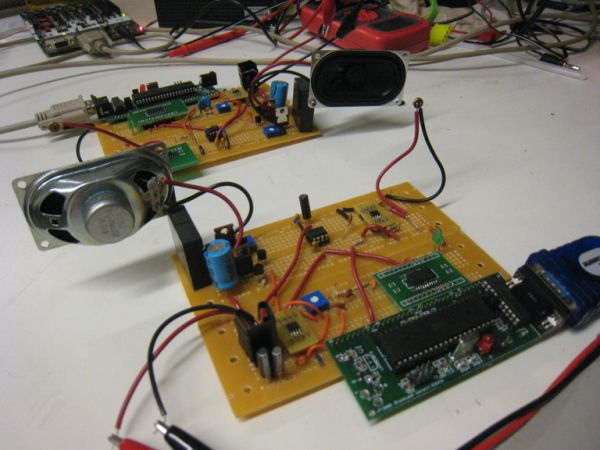
The hardware for the acoustic modem is relatively simple. It can be broken into four sections: power management circuitry (1), Microcontroller circuitry (2), speaker driving circuitry (3), and microphone processing circuitry (4).
Power Management – The power managment circuitry consists of an LM34T05 Linear Regulator, which accepts an input voltage of about 9-12 V and produces +5 V. It is capable of driving up to 1 Amp of current without dropping below +5 V, which is necessary to support the class A amplifier implementation used to drive the speaker.
Microcontroller – The microcontroller circuitry is all housed on the custom PC board provided by Bruce Land. The schematic implemented on this custom PC board is reproduced in our schematic listing for completeness.
Speaker Driving Circuitry – An AD7801 D/A Converter is connected to PORT C of the Atmega644. It is driven in parallel with digital samples to be converted to an analog signal. The output of the DAC goes through a 2nd order passive low-pass filter with cutoff at 19.9 kHz to attenuate the high frequencies created by the edges on the DAC output. Next the analog signal is fed through an inverting amplifier with a potentiometer as the feedback loop, allowing us to modify the gain. This is important because the low resolution of the DAC makes it beneficial to synthesize a wave of as large amplitude as possible, but the actual speaker-driving amplifier is not rail-to-rail, so the signal itself must be less than 2.5 V in amplitude. Luckily, analog signals have infinite precision, so information is not lost (although SNR decreases a little bit) by applying less-than-unity gain through this operational amplifier. The output of the DAC is centered around a virtual ground of +2.5 V supplied by the MAX6325 reference, and this virtual ground is maintained up through the speaker driving circuitry.
The speaker is driven with the operational amplifier’s output buffered by a common-drain JFET stage followed by a common-collector BJT stage, biased by an active load implemented as an N-channel MOSFET current mirror. The reference current is implemented using a BJT connected by a potentiometer to VCC, allowing us to modify the load current after the circuit has been built, which helps adjust the parameters to account for variations in the discrete transistors used. Originally the op-amp drove the BJT CC stage directly, but when delivering high power near the positive rail, a strange type of instability occurred resulting in the synthesis of several waves in the MHz range. Adding the second voltage buffer to the op-amp output fixes the problem and delivers the wave to the speaker without significant distortion.
Parts List:
| Name | Part # | Vendor | Unit Price | Quantity |
|---|---|---|---|---|
| Microcontroller | Atmega644 | Atmel | $8.00 | 1 |
| RS-232 Level Shifter | MAX233 | Maxim IC | Free1 | 1 |
| 8-Bit Parallel D/A Converter | AD7801 | Analog Devices | Free2 | 1 |
| Single/Dual Rail-to-Rail Operational Amplifier | MAX4281/MAX4282 | Maxim IC | Free2 | 23 |
| +2.5 V Reference | MAX6325 | Maxim IC | Free2 | 1 |
| 3 Watt, 8-Ohm Speaker | 668-1125-ND | Digi-Key | $5.03 | 1 |
| Omnidirectional Electret Microphone | 359-1029-ND | Digi-Key | $1.50 | 1 |
| Custom PC Board | N/A | Bruce Land | $4.00 | 1 |
| Solder Board | N/A | 476 Lab | $2.50 | 2 |
| DIP Socket | N/A | 476 Lab | $0.50 | 3 |
| SOIC Carrier Board | N/A | 476 Lab | $1.00 | 3 |
| DB-9 Connector | N/A | 476 Lab | $1.00 | 1 |
| .1″ Male Header Pins | N/A | 476 Lab | $0.05 | 85 |
| N-Channel MOSFET | IRFZ34E | International Rectifier | Free4 | 2 |
| NPN BJT | 2N2222 | ST Microelectronics | Free4 | 2 |
| N-Channel JFET | 2N5457 | Fairchild Semiconductor | Free4 | 2 |
| 10k Potentiometer | Any | 476 Lab | Free4 | 2 |
| 1 uF Capacitor | Any | 476 Lab | Free4 | 7 |
| 0.1 uF Capacitor | Any | 476 Lab | Free4 | 6 |
| 22 pF Capacitor | Any | 476 Lab | Free4 | 2 |
| 1 nF Capacitor | Any | 476 Lab | Free4 | 35 |
| 2.2 nF Capacitor | Any | 476 Lab | Free4 | 1 |
| 500 pF Capacitor | Any | CUAUV Lab | Free4 | 35 |
| 20 MHz Crystal | Any | 476 Lab | Free4 | 1 |
| 680 uF Capacitor | Any Electrolytic | CUAUV Lab | Free4 | 1 |
| 8 kOhm Resistor | Any | CUAUV Lab | Free4 | 35 |
| 16 kOhm Resistor | Any | CUAUV Lab | Free4 | 35 |
| 2.2 kOhm Resistor | Any | 476 Lab | Free4 | 1 |
| 1 MOhm Resistor | Any | 476 Lab | Free4 | 1 |
| 2 kOhm Resistor | Any | 476 Lab | Free4 | 1 |
| 10 kOhm Resistor | Any | 476 Lab | Free4 | 1 |
| 560 Ohm Resistor | Any | CUAUV Lab | Free4 | 1 |
| 300 Ohm Resistor | Any | 476 Lab | Free4 | 1 |
| 100 Ohm Resistor | Any | 476 Lab | Free4 | 1 |
| Red LED | Any | 476 Lab | Free4 | 1 |
| Green LED | Any | CUAUV Lab | Free4 | 1 |
| Power Supply (shared) | N/A | 476 Lab | $5.00 | 1/2 |
| Total (per board) | $35.78 | 60 | ||
| Total (altogether) | $71.56 | 121 |
For more detail: Acoustic Data Modem Using Atmega644