Introduction
Elevator Pitch / 1-second Description
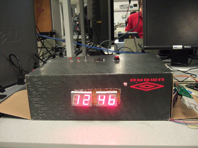
An adaptive alarm clock that chooses the optimal time to wake up the user using an accelerometer that detects his/her body movements.
Goals
The goal of our final project was to create an alarm clock that is able to detect your sleep patterns and wake you up at the optimal time, i.e. when you are in the lighter phases of sleep. Our goals for this project were broken up into several progressive milestones. The milestones are listed as follows:
Sleep Analyzer
Since the main goal of our project is to analyze one’s sleeping pattern, we considered many different sensors in order to detect this. We decided upon using an accelerometer in order to collect body motion data during the course of one’s sleep. Using accelerometer output, we hypothesize that one’s body motion during deeper sleep is less than during lighter sleep. We found that the accelerometer works in detecting body motion during sleep and our resulting data is presented in the rest of this document.
Adaptive Alarm Clock
After accomplishing the goal of obtaining sleep movement, we wanted to make use of this data in the form of an alarm clock to achieve the best wake-up time. Parsing the sleep movement data proved to be harder than expected. We came up with an algorithm that actively tracks and predicts the wake-up time. The algorithm for this wake-up time is described in detail later in this report.
Readback Mode
Finally, we needed a way to test and demo our alarm clock. We saved sleep movement data to an SD card and we were able to analyze this on a computer using Matlab. We then built in a readback mode, which runs the alarm clock at 100 times the speed and reads back accelerometer output from the SD card, simulating a night’s worth of sleep.
High Level Design
Rationale
The reason we chose this project was to build an alarm clock that could improve one’s sleep by simply picking a good time to wake up. Optimally, this would reduce the number of times one would hit the snooze button and one would wake up refreshed after a good night’s sleep. We also thought it would be interesting to analyze one’s movement during sleep.
Background Math
Very little background math is needed to understand our project. The alarm clock keeps track of time internally using military time (24 hours). We make use of simple mathematical concepts like averaging and counting in our algorithm.
Logical Structure
The logical structure of our program is to sample A/D conversions from the accelerometer and write those samples to the SD card. We also have to keep track of and display the time. We also had to set up an interface so that user could set an alarm time and turn off the alarm.
Our program was structured with multiple tasks with separate timers. There was a single timer 0 overflow ISR that interrupted every millisecond in order to keep track of time and set off task timers. The tasks in our program consisted of taking A/D conversions from the accelerometer, write read values to the SD card, update the LED display, check for button presses, and set off the buzzer. These tasks are fully described later in the software section.
Hardware/Software Tradeoffs
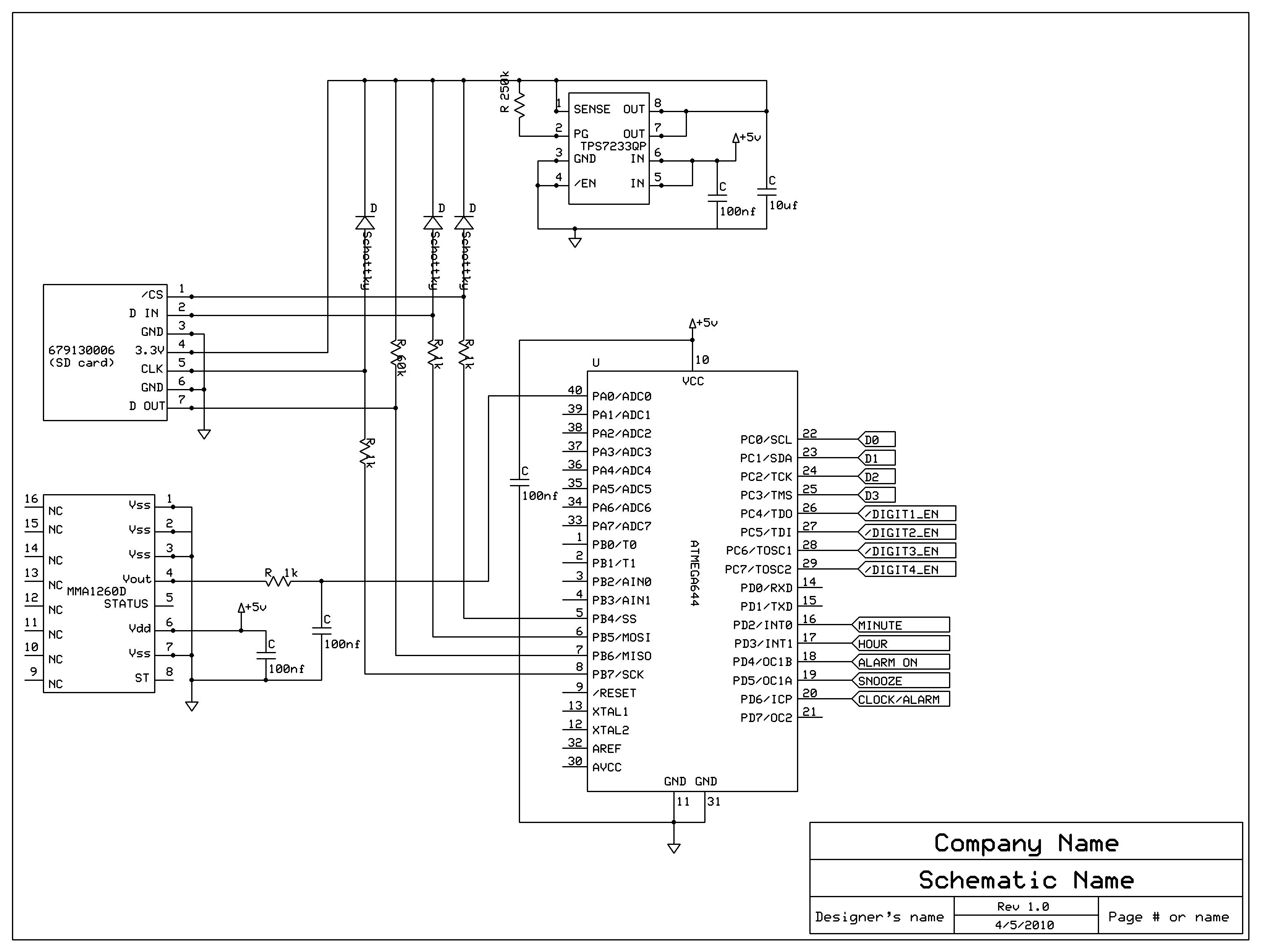
We used 4511 series BCD-to-7-segment decoders to greatly simplify the programming of the LED displays. Without them, we would have to drive the LEDs in the 7-segment displays individually and that could take up many MCU port pins. In order to minimize the number of pins used for the LED display, we connected the corresponding bits of the input to the decoders together. Since the decoder for each digit had a latch, we simply enabled the latch of the digit to update its value in the updateLEDdisplay function. Refer to the Hardware and Software sections for further discussion of design tradeoffs.
Relationship of Design to available IEEE and other standards.
We followed the standards according to the SD Association for using the SD card in MMC mode using SPI for communication. The FatFs library that we are using is a Windows compatible FAT file system. The RS232 standard was used for serial communication.
Existing patents, copyrights, and trademarks
There has been a lot of existing and related work in this field. We looked at several products on the market that offer the same functionality as our alarm clock. The closest product was an iPhone app called Sleep Cycle that makes use of the iPhone accelerometer to produce a graph describing one’s different sleep phases throughout the night. It makes use of this data to wake up the user. Other products include WakeMate, Axbo, and Zeo. They make use of a variety of sensors that are attached to one’s body to detect movement, pulse, and even brainwaves. A full listing of these products is listed in our references section in the appendix.
There exist several patents in this area that describe similar ideas but to our knowledge we have not been able to find a patent that is remarkedly similar to ours. The following is a description of several patents that we found to be similar to our idea. We found a patent for an adaptive alarm system that uses a motion sensor or video camera to track a person’s movement and to determine whether or not to adjust alarm clock signals accordingly. There has also been work in determine one’s sleep phase using the heart rate and pulse. Such a system is described in this patent. Finally, there have been models proposed that use a system similar to ours that uses a general sensor and a signal processing unit that analyzes the output from this sensor.
Hardware
ECE 4760 Custom PCB Board
We used the ECE 4760 Custom PCB board to create a board for our microcontroller. The full details about this board can be found on the ECE 476 webpage. Our final board included a Max233CP for serial communication and an RS232 connector. The board included an LED which we used to indicate whether or not the program was writing to the alarm clock. We powered our board using a 9VDC wall wart.
Accelerometer
Using this resource that we found online, we were able to determine which type of accelerometer to use. We tried out a few accelerometers with varying parameters. We found that the parameter that affected our performance the most was maximum swing. The accelerometer that we used was a Freescale MMA1260D. It is a Low G Accelerometer. It is a one-axis accelerometer with a maximum swing of +1.5g. We also tried 2-axis and higher maximum swing accelerometers. We found that the higher maximum swing accelerometers did not fit our needs since a person’s motion in bed is a relatively low-G activity. There were 2 key reasons for why we did not use a 2-axis device (or adding another one-axis device to acheive the same functionality). The first reason was that we found that the extra axis did not provide much more extra information, and simply reinforced the single axis device’s data. Secondly, it was also a design decision not to complicate our design by adding another accelerometer axis.
SD card
We used an off-the-shelf SD card for storing and reading back data. We used SPI to commmunicate the SD card with the microcontroller. The main challenge in doing this was stepping down the voltage from 5V to 3.3V. For this we used a 3.3V voltage regulator to step down the voltage.
Buzzer
We looked at a variety of alarm devices. Primarily, we needed to find an audible wake-up device. We looked at a variety of buzzers and their rated dB. Using a dB scale we found online for common sounds, we were able to find a buzzer of appropriate loudness. Secondly, we needed to look at the rated voltage of the buzzer. Most buzzers we looked at had a range of voltages corresponding to dB ranges. Using the dB scale, we aimed to find a buzzer around 100 dB and with a large enough voltage range so that we could vary the buzzer loudness (for ramping up buzzer loudness, so as to not jar the sleeping user). The buzzer we found had a voltage range of 3V to 28V and 90 dB sound level at 12 V. These characteristics allowed us to have flexibility in how we implemented the buzzer.
Parts List:
| PART | PART NUMBER | QUANTITY | SOURCE | UNIT PRICE | PRICE |
|---|---|---|---|---|---|
| — | — | — | — | — | $67.62 |
| Atmel Mega644 | 1 | 476 Lab | $8.00 | $8.00 | |
| 40-pin DIP socket for 644 | 1 | 476 Lab | $0.50 | $0.50 | |
| Custom PC Board | 1 | 476 Lab | $4.00 | $4.00 | |
| Wall Wart | 1 | allelectronics.com | $2.85 | $2.85 | |
| Header Socket/plug | 16 | 476 Lab | $0.05 | $0.80 | |
| Max233CPP | 1 | 476 Lab | $7.00 | $7.00 | |
| RS232 connector | 1 | 476 Lab | $1.00 | $1.00 | |
| Header Socket/plug | 14 | 476 Lab | $0.05 | $0.70 | |
| SD socket | 1 | Molex sample | $0.00 | $0.00 | |
| SD card | 1 | Previously owned | $0.00 | $0.00 | |
| Large Solder Board | 1 | 476 Lab | $2.50 | $2.50 | |
| Small Solder Board | 1 | 476 Lab | $1.00 | $1.00 | |
| 3.3V Voltage Regulator | TI TPS7233 | 1 | TI Sample | $0.00 | $0.00 |
| 8-pin DIP socket for TPS7233 | 1 | 476 Lab | $0.50 | $0.50 | |
| Accelerometer | Freescale MMA1260D | 1 | Sample | $0.00 | $0.00 |
| 1″ 7-Segment Display | SC10-21SRWA | 4 | Mouser Electronics | $2.52 | $10.08 |
| 4511 LED drivers | CD4511 | 4 | TI sample | $0.00 | $0.00 |
| SOIC/ST203 Carriers | 4 | 476 Lab | $1.00 | $4.00 | |
| Header Socket/plug | 32 | 476 Lab | $0.05 | $1.60 | |
| Header Socket/plug | 32 | 476 Lab | $0.05 | $1.60 | |
| Bread board | 1 | 476 Lab | $6.00 | $6.00 | |
| Large Solder Board | 1 | 476 Lab | $2.50 | $2.50 | |
| Large Solder Board | 1 | 476 Lab | $2.50 | $2.50 | |
| Power Supply | 1 | 476 Lab | $5.00 | $5.00 | |
| Button | 3 | 476 Lab | $0.00 | $0.00 | |
| Switch | 2 | 476 Lab | $0.00 | $0.00 | |
| Buzzer | 1 | Radio Shack | $5.49 | $5.49 | |
| Shoe Box | 1 | Previous Owned | $0.00 | $0.00 |
For more detail: Adaptive Alarm Clock Using Atmega644