Introduction
Our goal in this project was to build a pair of high-speed transceivers that could encode and decode optical signals modulated using Morse code conventions.
The project involved a few interesting challenges that we believed would be interesting to tackle. Interfacing a camera with a microcontroller is a difficult thing to do, due to the limited memory capabilities of most microcontrollers. Because of the limitations imposed, in order to properly use a camera with a microcontroller, resources must be intelligently applied and the circuit must be designed around the camera rather than the microcontroller. The project took shape around the idea of a optical endec transceiver because it demonstrates how you could design an algorithm to process the image data from a camera without a prohibitive amount of memory being used.
In the four weeks that were allotted to us to finish this project, we built two high-speed transceivers that take user input (via PuTTy), encode the sentence(s) into a Morse code sequence, and flashes its associated transmission LED accordingly. The other station uses its camera to snap many pictures in succession of the other’s transmission LED, and in counting the number of ‘dark’ versus ‘light’ frames, decodes the Morse code and displays the reconstructed sentence on its corresponding computer screen. A few special considerations that came up during the design process was the coordination scheme between the two stations. Since both stations have receiving and transmission capability, to limit collisions (which would result in mangled data) and/or incomplete transmissions, we designed a simple protocol that limits when a station can receive and transmit.
High Level Design
Due to processing limitations, we changed the direction of the project in the middle of the design period. Originally, we planned to design a line-detection algorithm using noisy data from actual outdoor environments, but after gauging the resolution of the data that could be procured with our camera (and the very limited memory resources of our microcontroller), we decided that such an idea would not be feasible with our current camera and microcontroller.
Therefore, we decided to choose an application that depended less heavily on image quality. After discussing alternatives with several other people (Bruce Land, Annie Dai, Samuel Anttila), we decided to design and build a Morse code endec transceiver. Logically, the design is relatively simple, and the behavior of each transceiver can be broken down into three parts, as summarized in the graphic below.
Transmitter/LEDs
The transmission functionality is implemented using a Mega1284 microcontroller and five high-intensity IR LEDs. To form a unique pattern for the receiver to recognize (and to ensure that the transmission LED is always in frame), four of the IR LEDs were arranged into a square; these LEDs are almost always on. The IR LED at the center is the transmission LED; the microcontroller modulates the light in accordance with the Morse code conventions.
Receiver/Camera
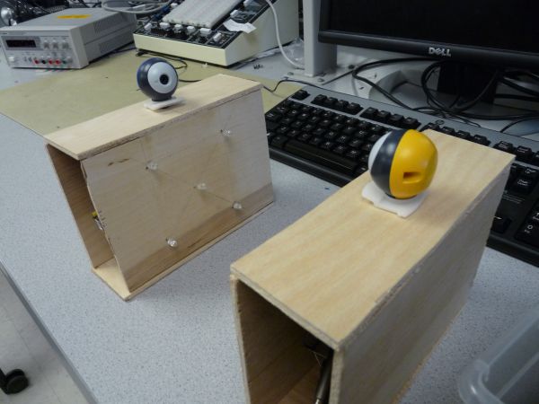
Likewise, the receiving functionality is implemented using the same Mega1284 microcontroller (used for transmission) and a M64282FP image sensor, which we left encased in the original Gameboy Color camera so we could take advantage of the lens. Since the possibility of additional light sources (besides the transmission LED) is very likely, especially in longer-distance applications, the camera detects the LED frame before searching for and reading the transmission LED (of the other station). The pattern of light flashes can be decoded by counting the number of frames that are dark (and light). Once the entire passage has been decoded into its respective Morse code, the pattern is matched it to a Morse code library and displayed on the screen at one time.
Transmit/Receive Protocol
To enable both transceivers to transmit and receive without loss of data, a simple receive/transmit protocol was designed and utilized. A transceiver can either transmit or receive; we decided to eliminate the possibility of doing both at the same time. For simultaneous receiving and transmitting, multithreading would have been necessary, which would significantly slow down our camera operation. Since decoding is dependent on a fast camera frame rate, multithreading would have constrained us to a much slower maximum LED blink speed.
Therefore, to coordinate the two modes of the transceiver, we need a signal that alerts the other transceiver that it is receiving/transmitting. In the case that A is the transmitter and B is the receiver, the protocol is as follows:
- When A wants to send, it sets all its frame LEDs bright.
- When B sees a frame, it turns on its own frame.
- Starting at this point, B cannot ask to transmit its own message.
- When A sees the frame, it sends a calibration signal (a dot followed by a dash, equivalent to the Morse code message “et”).
- When B sees the calibration signal, B counts the number of bright frames it has captured.
- A then begins to transmit and B begins to receive.
We performed a few back-of-the-envelope calculations to gauge the feasibility of this project. Our goal was to increase transmission via Morse code to the point that ordinary people could not look at the blinking LED and decode it faster than the microcontroller (for obvious reasons). For this to occur, we would need a very fast camera frame rate to decode the dots and dashes accurately. If each character takes an average of three dashes, and each word has about five characters, and each sentence has about ten words, then the average sentence would be about 3x5x10 = 150 dashes. If we want to take about 5 seconds to transmit the sentence, then each dash must be about 0.03 seconds long, which means that each dot must be about 0.01 seconds long, which translates to a frame rate of 90 frames per second, assuming that each dot can be accurately captured in one frame of the camera. Since this is much much much faster than our camera can support, it was likely that something on the order of 10-15 second transmission would be achieved.
To ease the load on the software, we set up our physical display so that any complicating external factors, such as external light sources, were mostly eliminated. The hardware/software tradeoffs that we mostly looked at during project design included eliminating the use of an ISR (to reduce code complexity); the hardware bits that directly controlled the camera were set using a simple sbi() command after the appropriate amount of time had elapsed, which made the code very simple and very fast. The _delay_us command was used for this purpose, since after the threshold hold time is met, the exact time is not of much importance. Furthermore, because of the very limited memory of the Mega1284 chip, the data from the camera had to be stored in memory in a very compact format. Although we used the unsigned char data type for the majority of the variables to save space, a char array consisting of 16384 elements would still have exceeded the memory capacity of the microcontroller. Therefore, in software, a few lines of code were written to quickly and effectively create a bit array to store the digitized values of each pixel.
Our design falls under a more general class of devices that utilize free-space optics. Because this technology is not yet very prevalent, there are not very many standards governing the design of such devices. However, IEEE 802.15.7 details the standards for a very similar technology, visible light optical communication. This document provided valuable guidance to us during the design process: it shaped our consideration of the modulation process and led us to consider the possible topologies of our device.
As far as we know, our project does not violate any copyrights. Although there are several VLC systems that are on the market, our modulation scheme (chosen to support a slow camera framerate) and transmission/reception protocol are unique.
Hardware Design
The hardware that we used in our project is as follows:
- two Mega1284 microcontrollers
- two M64282FP image sensors (complete with lens)
- ten high-intensity IR LEDs
- resistors: 6x 330Ohm, 4x 2kOhm, 2x 1kOhm
Each transceiver consisted of one microcontroller, five high-intensity LEDs, one M64282FP image sensor (inside the Gameboy Camera), and one 200 Ohm resistor.

Several resources were consulted [1][2] when interfacing the Gameboy Color camera with the microcontroller. The M64282FP image sensors are unique in that they already come interfaced with a CMOS chip that does elementary image processing (therefore cutting down on the thresholding processes that needed to be performed on the microcontroller, which allows for greater operation speed). Furthermore, this camera/chip ensemble has a clear datasheet and iis well-documented in many hobbyist AVR groups, which increased its attractiveness.
Parts List:
| Part | Source | Unit Price | Quantity | Total Cost |
|---|---|---|---|---|
| Total | — | — | — | $68 |
| Gameboy Camera/M64282FP Image Sensor | Ebay | $10 | 2 | $20 |
| Mega1284p MCU | ECE4760 Lab | $5 | 2 | $10 |
| IR LED | ECE4760 Lab | $1 | 10 | $10 |
| Serial UART Extension | ECE4760 Lab | $4 | 2 | $8 |
| Header Pins | ECE4760 Lab | $0.05 | 100 | $5 |
| Sockets | ECE4760 Lab | $0.05 | 100 | $5 |
| Plank of plywood | Lowe’s | $10 | 1 | $10 |
For more detail: Alphanumeric Optical Endec Transceiver Using Atmega644