Many AVR microcontrollers are capable of doing Analogue to Digital Conversion. The ATmega168 has 6 ports (8 ports on the SMD packages) that can be used for analogue input. This tutorial shows you how.
The circuit
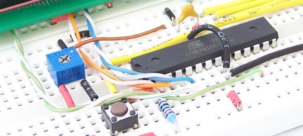
The Breadboard layout is based on the Atmega8 breadboard circuit which is described in Atmega8 breadboard circuit Part 1 and Atmega8 breadboard circuit Part 2.
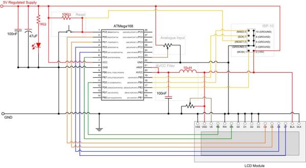
AVCC
The Atmega168 has 2 digital supply voltage pins, VCC and AVCC. AVCC supplies power to PC0-PC5. When these pins are used as analogue inputs, the AVCC power needs to be very stable. This is achieved by using a low pass filter comprising of an inductor and capacitor.
AREF
The AREF pin is used to set the voltage that corresponds to a 100% value (1024) in the AD converter. In this example we tie it to AVCC.
Analogue Input
The Atmega168 has has 6 pins (8 for the SMD packages) that can be used for analogue input. These are PC0 to PC5. These are normally used for digital I/O but can be used for analogue input as well. In our example we are using a trimpot as the analog input device and connecting it to PC0.
Read More: Analogue to Digital Conversion on an ATmega168