Throughout this USB series, different types of USB devices have been designed and developed. These devices were enumerating with the host computer and then were using Class Specific transfers for further USB communication. Like the Keyboard, Mouse and joystick devices were using interrupt transfers for their operations after enumeration. Similarly, the audio class devices were using isochronous transfers for their operations after enumeration. The CDC Class devices were using bulk transfers for their operations after enumeration. Any of these transfers (Bulk, Isochronous or Interrupt) are enabled only after the control transfer which let the device get enumerated with the host. These transfers are required when data is also sent from the device to the host computer.

In this project, an USB device to control an LED series will be designed. The device will not send any data to the host computer but will only read data from the host computer and control LEDs accordingly. In such type of USB communication, only control transfer is sufficient to implement the device functioning and so only Endpoint 0 is involved in the USB communication.
The project will need a controller chip to handle USB data from the computer and to operate LED series accordingly. The 8-bit USB AVR – Atmega 32u4 is used as the device controller chip in the project. The project uses AVR based Lightweight USB Framework (LUFA) as the firmware which will be modified to implement the project’s functioning. The device is tested on a Linux system using Pyusb and Libusb frameworks for sending data from computer to the device.
The Generic HID device driver class of the LUFA firmware is used and modified to program the project. With the use of LUFA firmware, the device driver code to implement USB protocol is not needed to be written explicitly. Modifying the firmware code will be sufficient to implement the USB protocol. The device has four LEDs connected to it which will be switched ON or OFF from the computer.
PREREQUISITES
This project is based on Arduino Pro Micro which has the USB AVR – Atmega 32u4 as the sitting MCU. In order to understand this project, one must have basic knowledge of the AVR microcontrollers and the embedded C programming for AVRs. WinAVR Studio is used to write, edit and compile the project code, so closely following the project shall require familiarizing with the above stated IDE as well. Though LUFA framework takes care of implementing the USB protocol and has APIs to abstract the lower level codes, understanding USB protocol is recommended to understand how actually the project is working. In fact, if anyone has already worked on some other microcontroller, it will not be much pain to understand and follow this project as the project code is more or less about modifying the LUFA device driver to work as generic HID device and receiving digital output at the Arduino pins.
COMPONENTS REQUIRED
1. Arduino Pro Micro
2. Breadboard
3. Connecting wires
4. LEDs
5. Micro USB cable
6. 10K resistors
SOFTWARE TOOLS REQUIRED
1. WinAVR Studio
2. AVR Dude
3. LUFA Firmware
4. Python 2.7.12
5. Pyserial 2.7
BLOCK DIAGRAM
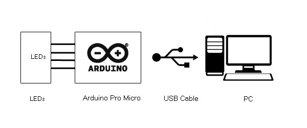
CIRCUIT CONNECTIONS
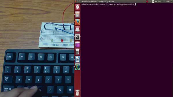
The project uses Arduino Pro Micro as the USB controller chip. A series of four LEDs is connected at the port B of the Arduino. The LEDs are connected at pins 2, 4, 5 and 6 of the port B. The 220 Ω pull up resistors are used to interface the LEDs. The LEDs are connected between the pins and the ground with anode connected to the pin and cathode connected to the ground. Therefore, when a HIGH logic is output from the pin, the LED starts glowing and when a LOW logic is output from the pin, the LED stops glowing.
The Program code for the project is burnt to the Arduino Pro Micro using AVR Dude. The Arduino board is connected to the USB port of a PC by a USB cable.
HOW THE PROJECT WORKS
In this project the USB protocol is implemented by the LUFA framework. For configuring the controller chip to work as Generic HID device, the HID Class Driver of the LUFA framework will be used. The Human Interface Device (HID) class takes care of the transfers between the host device and the human controlled USB peripherals like USB Keyboard, Mouse or Joystick. However, the Generic HID device made in this project only handles to receive data from the host computer.
When a USB device is attached to the host (PC), the host sends request for configuration details in the form of control transfer. The connected device has to respond with appropriate descriptors to get configured and ready for further operations. Only after configuration, the device can communicate with the host in the form of interrupt, isochronous or bulk transfers for executing the operations for which the device has been made. This process of identification and configuration of the device with the host is called enumeration.
In case of LED series, after configuring with the host device, it has to communicate with the host in the form of control transfers only for reading data from the host computer. The Control Transfer can also be used to exchange data between Device and PC like the other transfer types. The Class Specific Requests of Control Transfer will be used to send data from Host (PC) to the Device (Microcontroller).
In HID class, two types of Transfer Types are used: Control Transfer and Interrupt Transfer. Generally, the Interrupt Transfer is used to send Data Reports. But the Control Transfer can also be used when Interrupt Endpoints are not declared or available. The Default Control Endpoints (Endpoint 0) are always available so control transfer can also be used to send or receive data anytime. The data can be exchanged using Class-Specific Requests. These Requests are sent by Host to Device via Control Transfer. The Set_Report is the request by which Host can send data to Device. The Set_Report request is structured in the following manner -:
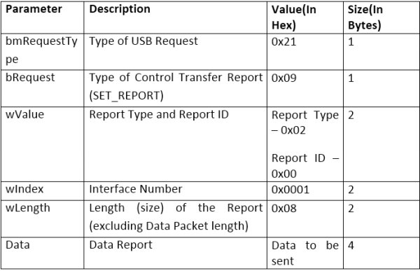
The data will be transferred using Data Packet or Data Report. The Data Report (Data Packet) will contain four bytes. These bytes will be used to indicate the device to switch ON/OFF the LEDs. Therefore the LEDs and data report received by control transfer from the host computer will be related in the following manner -:
Read More: Atmega 32u4 Based USB Controlled LED Series