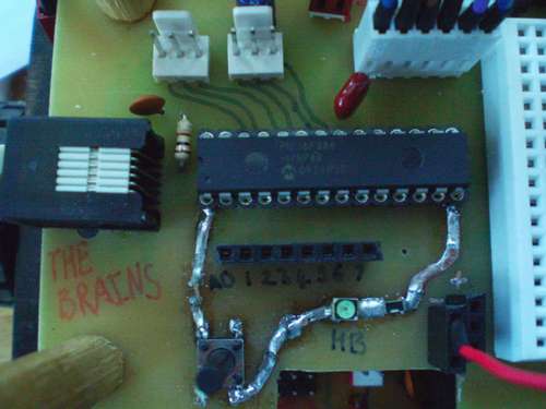
This instructable will guide you through the generic steps of designing and building an augmented microcontroller board. I have purposefully made it generic so that I do not limit it to a particular make or model of MCU, and I’ll try to mention alternative ways of doing things to make it a bit easier for you.
I’m going to be designing and making an augmented microcontroller board for a 28 pin Microchip PIC, the 16F886. My example is going to be for a robot, so I’m going to include motor driver circuits, digital and ADC headers and some indication LEDs.
A generic list of materials/tools:
MCU and assorted supporting components (caps, resistors, headers)
A breadboard for prototyping
Some way of permanently building the circuit (I’ll be etching copper board)
So — let’s get started.
Step 1 Designing the Main Circuit
For the purposes of this instructable I’m assuming that you’ll be programming a blank MCU via some sort of in-circuit programming interface (I’m using Microchip 6 pin ICSP). Bootloaders and USB programming are a bit out of my programming depth as of writing!
The most obvious element of the circuit is the microcontroller. Surrounding it will probably be:
Power Supply Regulation
Reset Switch
Programming Header
External Clock (If you need one)
Port headers
Let’s deal with these one at a time…
Power Supply Regulation
Your MCU and surrounding circuitry will probably run at either 5v or 3.3v. I’m using 5v, but similar methods apply for 3.3v. There are two main types of DC-DC power regulation, linear and switching. Linear is easy, switching is more efficient. Linear involves one device, usually a three pin IC, and some capacitors, whereas switching will require a larger IC and various other components.
You need to include at least three power supply caps: ~10uF Aluminium across the unregulated supply, ~4.7uF across the regulated supply, and 0.1uF ceramic across the power rails of the MCU. If you don’t have one elsewhere in your circuitry, you should have a ~300uF aluminium cap across the unregulated power too. A power indication LED is nice, too. One in series with a 1K ohm resistor, running off the regulated power is a nice touch. Make it green. We like green.
Reset Switch
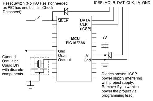
Most MCUs have some sort of reset or mclear pin that, when bought to a certain state, resets the MCU and makes it start it’s program again. On the PIC16F886, this pin should be held high to enable the MCU to operate, but we’ll add a reset switch which momentarily brings it low, resetting the MCU if we need to. Some MCUs have built in P/U resistors, so just a switch to GND is needed.
Programming Header
This is where the MCU connects to your computer to receive it’s program. PICs and AVRs both use six pin headers, but in different formats. I’ll be using a 6 pin RJ-45 socket, as they’re hardy and will put up with me constantly plugging and unplugging as I try desperately to correct the errors in my programs! Consult relevant datasheets to see what the pinout of the connector is, and which pins of the MCU they need to connect to.
Sometimes there can be problems with adjacent data/clock lines, and some people recommend putting an R/C filter on one or both of the lines. This can help reduce crosstalk and interference, meaning less headaches later on. I’m not including a filter in this project.
External Clock
Not all MCUs have an internal oscillator (an oscillator somewhere is required to give the MCU a synchronised ‘beat’ that all of it’s sub-systems can work to), and even if it does, you might want a particularly high/low operating frequency, or a more accurate beat for intense timing applications. These can take various forms:
R/C Oscillator: Cheap and inaccurate. Only use this if your MCU has no int. oscillator, and you don’t want to spend any money.
Crystal: More accurate and the metal cans look awesome on a PCB 😉 They will require a couple of small caps. to function.
Canned oscillator: Is essentially a crystal and the caps in a little box/ceramic (as shown by schematic). I’ll be using one of these.
Port Headers
These are usually very simple: A male or female header, connected to relevant pins. You could also use terminal blocks for more heavy-duty use. Most MCUs will not need Pull up/down resistors, but you might choose to add them to ‘default’ the pins to high/low. I suggest 47K-67K ohms, to +V or Gnd.
On the other hand, you might choose to add some extra circuitry between the MCU and the external connections. Leading conveniently onto the next step!
Step 2 Designing Auxiliary Circuits
If you want to make an ultra-multipurpose, generic microcontroller board, then what I’ve covered already is enough. It’s the bare basics that will get your MCU up and running and expandable. But if you want to make yourself something a bit less generic, more powerful, application-specific and cool-looking (i.e. a really augmented microcontroller), then consider adding some extra circuitry.
This is for a mobile robot, so I’m adding two MOSFET H-Bridge motor drivers (the schematic for one is shown). But you could add an LCD screen, USB/Parallel communication hardware, supporting circuitry for photodiodes, etc. Depending on your level of ability, maybe even some kind of bluetooth, WiFi or other RF communications facility!
Basic principles of circuit design apply: Whatever you add must run off the same power supply as the rest of the circuit (Actually, my motor drivers will partially use unregulated power, but they share a common ground). It must not generate noise that interferes with the MCU, must not create large voltage spikes that could destroy the MCU, and must interface with it at current/voltage levels that the MCU can provide (hence the 4427 driver, not just a direct connection to the MOSFETs).
So for my motor driver, I’m going to use 4427 chips to drive the MOSFETs, controlled by the low current 5v signals from the MCU. I’m going to include EMF protection diodes, and capacitors of various sizes and chemistries to support the circuit’s power requirements. In practical terms, this means: a 47uF Electrolytic Capacitor and a 20uF Tantalum cap. in parallel across the power rails, and a 0.1uF ceramic/other cap. across the power rails of every IC, just like on the MCU.
(A tip for recognising MOSFET types from the diagram: The arrow always points to N semiconductor)
I’m also going to add two LEDs, a green and a yellow, controlled by the MCU. They just need a 1K ohm resistor in series with them, and they can plug straight in to a spare pin. They’ll be used as generic indicators, which are very useful during debugging.
For more Detail: Augmenting a Microcontroller using AVR

