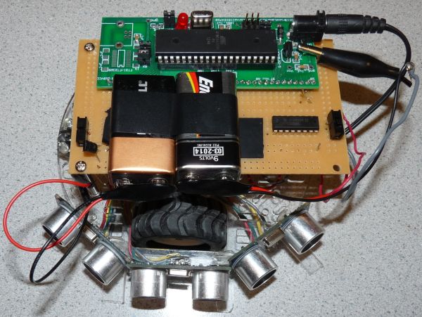
This project is intended to perform the role of a goal-keeper in the popular arcade game Air Hockey. In this project, the robot shown below senses a puck coming toward it and moves in the direction of the puck’s motion so as to stop it. This problem was identified as fairly challenging to solve based on two metrics. Firstly, Air Hockey is fast paced and designing a highly responsive control system seemed exciting. Secondly, most prior solutions to this problem have been attempted with robot arms that are vastly greater in cost than the solution presented in this project.
High level Design
The robot is designed to be an autonomous entity, in that it is battery powered and does not require human input to locate a moving puck in a game of Air Hockey. So as to behave optimally, the robot is most likely to lurk around the region near the goal rather than move end to end while tracking the puck. This is due to an optimization in sensing distance that we felt necessary to introduce in the sensing mechanism of the robot as discussed in the Hardware section. Overall, the robot performed well in the absence of a lot of noise from other sensors in the environment. Even so, owing to the nature of the sensing, i.e. sensing planar sound waves with ultrasonic sensors, there was notable loss of sensitivity in sensing. This was improved by altering the geometry of the puck as shown in the Pictures section.
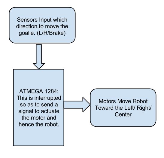
Shown below is an illustration of the system as a whole. The ATMEGA 1284 MCU takes in echo patterns from each of the sensors, interprets them and accordingly actuates the robots motors.
hardware
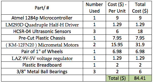
The hardware employed in the project spans some fairly basic elements, each of which will be described in detail. A listing of the components includes:
- 1 Atmel 1284 Microcontroller.
- 1 LM293D Quadruple Half-H Drive
- 3 Ultrasonic Sensors.
- 1 pre-cut circular chassis.
- 2 30:1 Micrometal Gearmotors with mounting brackets.
- 1 pair of wheels.
- 2 9V batteries.
- 2 SPDT switches.
- 1 LAZ 9V-5V voltage regulator.
- 1 PCB-like Plastic Breadboard.
- 3 metal spacer mounts to mount the breadboard.
- 2 3/8″ metal ball bearings.
The system can be broken into two main subsytems – sensing and actuation. The sensing subsystem takes in inputs from its surrounding and interrupts the microcontroller when it senses a moving puck. The 1284P microcontroller (MCU) then uses this interrupt to signal the acutation subsystem to move the robot in the appropriate direction as required.
-
Sensing Subsystem
As shown below in Figure 1, the Sensing subsytem is comprised of the MCU receiving inputs from 3 ultrasonic sensors.
- The system above represents the bulk of the interaction between the MCU and Sensors in our system. The sensors were placed in a V-Shape as in Figure 2 so as to capture and track any possible change in the movement of the puck; the exact functioning of this is described in the next paragraph.
- Consider the event that the puck moved from somewhere in between the center and right sensors toward the left. When the puck intersects the trigger pattern of the left ultrasonic, this would actuate the motors on the robot, via the left ultrasonic’s echo, to make it move toward the left and continue to move toward the left until the puck intersected the trigger pattern of the center sensor; which is when the brake would be applied, causing the robot to stop in its tracks. The same applies for when the puck moves from somewhere in between the center and left sensors toward the right.
- In the event that the puck is sent straight down the board, the robot would trivially detect, stop it and not move at all.
- Finally, considering that the puck was banked perfectly on one of the edges of the air hockey table, we figured that the puck would need to hit the edge a minimum of 2 feet away from the robot to make a decent attempt on goal. We therefore narrowed the range of the ultrasonic sensor to around 1 foot so as to fully encompass a region of interest for the robot without the opportunity of letting it get confused or lose information off of the edges of the air hockey table. This implies the robot should move only within the area on the Air Hockey table that is near the goal it is attempting to defend.
To sum up this section, it would seem useful to talk about why the HCSR-04 (See Figure 3) and more importantly, why ultrasonic sensors, were chosen as a sensing mechanism for this project. The HCSR-04 was picked through a process of elimination and after carefully going through every alternate sensing mechanism available to us. This included Infra-red, lasers as well as better ultrasonic sensors. Initially it was posited that the use of lasers would provide the most accurate sensing data for a moving object, i.e. the puck, to feed data (in the form of a stable interrupt) to our MCU. However, there were several issues with this. To begin with, we were constrained by a tight budget and employing a set of three laser emitter and receiver pairs was deemed too expensive given that we required quick and responsive DC motors to actuate the robot in the direction of the puck; these motors represented a fixed and relatively high expense in themselves. We then moved on to infra-red, but given our inability to deploy this effectively in lab, we decided to scrap this idea. Finally, after looking at several ultrasonic sensors and their datasheets online, we decided to settle on the HCSR-04 as it had the range we needed to operate within and was fairly inexpensive as well. Even so, apart from this, the HCSR-04 represents a very flexible mode to sensing, allowing the opportunity for a designer to easily vary the range of the sensor based on how long and how often the trigger signal is applied to it. This represents some clear benefits given that this sensor can thereby be mounted on chassis of varying heights as it has a fairly wide angle of 15 degrees to receive the echoes of the signals it sends out.
Parts list:
For more detail: Autonomous Air-Hockey Goalie Using 1284