Sometimes when tuning various electronic hardware we need simple signal generator with various waveform and frequency. One of the options is to by a professional with variable gain professional coating and many additional functions. But if you are an amateur you might want to build one. This small project is dedicated for building one of those signal generators.

Specification
AVR DDS signal generator consists of following parts:
- Atmel Atmega8 8 bit microcontroller;
- Supply source and voltage regulator;
- 2×16 standard LCD and shift register 74HC164;
- 7 buttons;
- R-2R resistor leader for DAC;
- Three outputs: universal(OUT) from DAC, PWM and pulses;
- Metal case;
- and microcontroller firmware.
Atmega8 microcontroller is a simplest of atmega series. There is 8kb of FLASH program memory, maximum frequency is 16MHz, which is used to reach DDS generators maximum resolution at maximum frequency. For know frequency is limited from 1 to 65535Hz with minimal step of 1Hz.
DDS AVR generator is powered with 9V battery. Voltage is reduces to 5V and stabilized by 7805 voltage regulator.
LCD is controlled using three wires through shift register 74HC164. So this register is used as serial to parallel converter in order to save microcontroller pins. LCD is controlled in 8 bit mode.
AVR DDS Generator uses 7 control buttons:
- Start;
- Stop, which is a reset also;
- IP- increasing value;
- DOWN- decreasing value;
- Mode1 – signal selection button;
- Mode2 – signal properties;
- Freq – signal frequency multiplier selection.
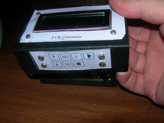
Buttons on the box
AVR DDS signal generator uses R-2R digital to analog (DAC) converter This is a simplest solution where resistors are connected in a ladder:
In this schematic R=10kohm. By using 8 bits and 5V step value is about 18.5mV. This is enough for getting average quality signals.
Generator has three outputs:
- Universal DAC output through R-2R ladder;
- PWM;
- Impulse (SQ);
Universal output (OUT) is a signal output from DAC. This output is to form various signals like sawtooth, sine, square, triangle.
PWM channel is used to form for PWM signal output – directly from timer.
SQ channel is additional channel to form square pulses or second PWM signal. Will be implemented in future.
For more detail: AVR DDS signal generator V1.0 using ATmega8