Introduction
We created a wireless device to affix to the bottom of a pitcher that alerts the wait staff when the pitcher is empty.
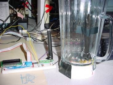
We used the a priori knowledge that when a pitcher is empty the pitchers bottom is perpendicular to the ground. By affixing an accelerometer to the bottom of a pitcher we can detect the angle of the bottom in relation to the ground. There is a direct correlation between the maximum angle the pitcher has reached and the volume still in the pitcher. We use this fact to monitor the pitchers volume through a wireless connection. The signal from the accelerometer is transmitted at 433MHz directly from the pitcher to the server station. The server station consists of an LCD and an array of control buttons that reset the meter, change the table number, and reset the pitcher count.
High Level Design
Rationale
Our decision to create the beverage monitor for our project was due to a combination of factors. The stroke of genius came when Erin remembered hearing about a bar in Japan that implemented a system that alerted the wait staff of when an individuals drink was empty. This appealed to us for 2 main reasons. Matt recalls many nights frequenting a local bar, The Royal Palms. All too often he was unable to locate a waitress and place an order before last call. His frustration along with Erins desire to create a potentially marketable and original project gave birth to the implementation of the beverage monitor.
Background Math
We monitored the tilt of the pitcher using the duty cycle output of our accelerometer. The MCU measures the rising edge pulse width, T1, and the total length of the duty cycle, T2. The acceleration is calculated by the following equation:
Then the arcsine of the acceleration is taken to find the angle of the tilt. This angle correlates to the volume of the pitcher.
In order to minimize the influence of invalid angle readings as a result of the wireless connection, Professor Land showed us a simple low pass filter to use:
Y(t) is the calculated angle, x(t) is the current angle reading, and y(t-1) is the previously calculated angles. The parameter α was determine through trial and error during testing.
Logical Structure
Our overall project design can be reduced to three specific states that can be seen in the state diagram below. The first state, the state entered at the beginning of the programs execution, is the Set Table state. In this mode the wait staff can select the table that they are serving. The selection is made by using two buttons, one to increment the table number and one to decrement it. Once the correct table is selected, the enter button is hit and the program then goes into Monitor mode. In this mode the wireless device on the pitcher sends the signal from the accelerometer to the server station. At the server station, the wait staff can see the number of the table being served and how many rounds have been served to the table. There is also a status bar showing the status of the pitchers volume. The MCU at the server station uses the signal from the pitcher to calculate its volume. In this state, there is a reset button in case a different table is about to be served. Unless the reset button is pressed, the program will stay in this state until the pitcher is empty. Once the signal indicated the pitcher is empty, the last state, the Refill state, is entered. Here the server station indicates that the table needs a refill. Once the wait staff refills the pitcher they press the enter button and the project returns to the Monitor state, and the additional round is indicated on the display.The reset button can also be used in the Refill state if the table decides not to go for another pitcher.
Hardware/Software Tradeoffs
When we implemented the receiver and transmitter our results were less than perfect. The problems occurred as a result of noise and antenna related issues. There were both hardware and software solutions at our disposal. We first tried hardware when we found that the edges in the output signal of the receiver were not as square as we had hoped and this adversely affected the input capture mode. Professor Land suggested adding a Schmitt Trigger to provide a clean square wave. This slightly altered the ratio of the pulses but improved the overall consistency of the signal. The altered ratio was handled in the software calculation. This was much better than any potential software solution due to its effectiveness and ease of implementation.
Later we found that we were getting invalid angle readings that were due to noise and interference with our transmissions. We could have implemented a hardware filter but instead Professor Land showed us a simple digital filter that we could implement in our code. This solved the majority of our issues and was an adequate solution.
Standards
The FCC sets aside frequencies between 420 MHz and 450 MHz for Amateur use, thus we are complying with the standard by transmitting our signal at 433MHz.
Existing Patents and Intellectual Property
We have been able to find technology developed by Mitsubishi Electric Research Laboratories that has been developed for the same function as our beverage meter. However, our solution to the problem uses completely different technology, thus we would not have a problem with existing patents, copyrights, or trademarks. Using an accelerometer was an original idea that has not previously been implemented.
Program and Hardware Design
Software Design
For our project, software is used for two specific purposes, reading and calculating the orientation of the pitcher and providing a user interface for the LCD at the server station.
In order to measure the length of the rising edge pulse and the total length of the duty cycle, we use the Timer 1 input capture mode. This mode triggers an interrupt on a rising or falling edge on pin D6, depending on the control settings. Along with triggering an interrupt, the capture mode saves the value of the timer 1 into a reserved register. In our specific interrupt we first read the value from the reserved register. This was tricky to code because the counter value is in a 16 bit register and the MCU only has an 8 bit bus. It turns out that when reading 16 bit registers the lower half must be read first and then the upper half can be read. In the case that the interrupt is entered as a result of a rising edge, the counter is set to zero. In order to do this, first the high 8 bits must be written and then the lower 8. Finally, the edge that triggers the interrupt is toggled, either from rising to falling or visa versa.
Once these values from the counter are saved in the interrupt, a flag is thrown implying there is valid data is ready to be used. When this flag is high, software outside of the interrupt calculates the ratio of the length of the rising pulse to the total length of the duty cycle. This value is used to calculate the acceleration on the given axis. The arcsine of the acceleration is then calculated to find the pitchers angle. This angle is not the angle used for analysis however. The calculated angle is first put through a low pass filter, and the result of this calculation is the value used for volume analysis.
In regards to the user interface, a simple state machine is used. Each of the states is contained in a method and the actual state machine is written in the while(1) loop in main. For the Set Table state, a second timer, timer 0, is used in order to drive the button debounce state machine seen below. The debounce state machine is used to debounce the two buttons, buttons 1 and 2, which are used to increment and decrement the table number. Button 3, the enter button, when pushed transfers the state machine to the Monitor state. In this state the interrupt for timer 0 is disabled and the one for timer 1 input capture is enabled. The pitchers orientation is monitored as discussed earlier and a simple status bar is displayed on the server stations LCD. The status bar is implemented by changing blocks of the LCD from a dark solid square to a large oval when certain predefined angles are reached. Once the pitcher reaches a given angle, the state is changed to refill and text requesting a refill is output to the server stations LCD.
Hardware Design
The hardware in our project boils down to two main parts, the accelerometer and the receiver/transmitter pair.
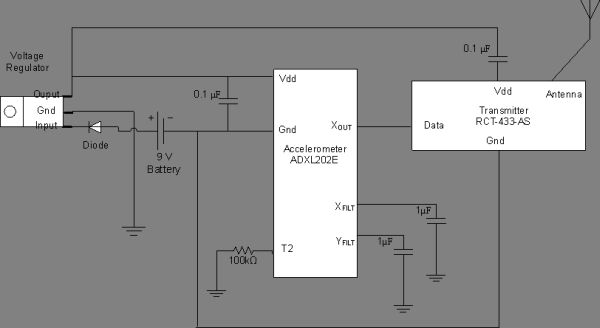
The accelerometer we used, the ADXL202EJ, has two types of outputs, analog and duty cycle, and two axes to measure the tilt, X and Y. Because we were planning to attach the accelerometer to the bottom of a pitcher, we wanted to avoid requiring an MCU for signal processing before transmitting.This limited our options. We chose a pitcher specifically because the handle forces a user to tilt in a given axis. We arbitrarily chose to use the X axis output on the accelerometer. We also decided that because this signal is going to be transmitted wirelessly and without encoding, the duty cycle output would result in cleaner results. In order to set the length of the duty cycle, we chose a 100 kΩ resistor, which set the duty cycle length to approximately .8 ms. We also added 1 F capacitors to the X and Y filt in order to limit the bandwidth to 1 Hz. We limited the bandwidth to the degree that we did because we were dealing with pouring a pitcher, a slow action.
The receiver and transmitter were easy to setup however minimizing the noise and maximizing quality transmission were not. After many different antenna designs we decided on a helical antenna. This helped compensate for the fact that the orientation between the transmitters and receivers antenna was changing often, e.g. pouring the pitcher.
The complete design of the pitcher attachment and the server station can be viewed in Appendix B. The pitcher attachment was powered with a 9 Volt battery. Between the battery and the rest of the hardware we added a power regulator that reduced the voltage supplied to the transmitter and accelerometer to 5 Volts. A diode was also attached as a safeguard if we happen to connect the battery backwards. The Xout port of the accelerometer was directly wired to the data port of the transmitter, and the antenna transmits to the server station.
The server station is powered by the STK500 board. The receiver has two different outputs; we use the data output. In order to clean up the received signal, we take the output of the receiver and put it through a Schmitt Trigger before we pass it to the MCU. The Schmitt Trigger output provides the MCU a clean square wave for the input capture pin.
Things That Didnt Work
When we had problems with invalid values, we tried many different software solutions. One solution that we attempted was the median filter. We created 2 arrays, one to save a given number of past angle values and one to sort the angle values from lowest to highest. We then took the middle value as the angle to analyze. This worked to an extent, especially when we increased the number of past values saved. This however put a large burden on the space and computational resources we had at our disposal. We found that the low pass filter was a much easier and more effective fix to our problems.
Results of the Design
Speed of Execution
When testing the project there is no perceived delay between when the pitcher has reached an angle implying emptiness and when the LCD displays a refill is necessary. The angle of the pitcher is monitored and calculated within our code at a rate much greater than an individual could ever pour a beverage out of a pitcher, thus the speed and concurrency is sufficient.
Parts List:
|
Quantity |
Part | Price |
|
1 |
Mega 32 MCU | $8.00 |
|
1 |
RCR-433-RP Receiver | $4.00 |
|
1 |
RCT-433-AS Transmitter | $4.00 |
|
1 |
ADXL202JE Accelerometer | $0.00 (Free Sample) |
|
1 |
LCD | $5.00 |
|
1 |
White Board | $5.00 |
|
1 |
DM74LS14 Schmitt Trigger DIP Pack | $0.40 |
|
1 |
Diode | $0.50 |
|
1 |
5 Volt Voltage Regulator | $1.00 |
|
1 |
9 Volt Battery Header | $0.50 |
|
1 |
9 Volt Battery | $2.00 |
|
1 |
Pitcher | $8.79 |
|
|
TOTAL | $39.19 |
For more detail: Beverage Monitor Using Mega32