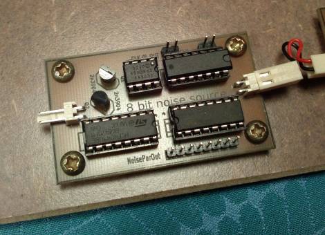
Motivation
I was building some Lo-Fi CMOS synthies, just like the ones you see here:
http://hackaday.com/2015/02/04/logic-noise-sweet-sweet-oscillator-sounds/
or here:
http://www.nicolascollins.com/hackingtutorial11.htm
Soon after I played around with some simple sequencers and multiplexers to generate more complex sound patterns. I thought it would be cool to have a device to gate oscillators or switch multiplexers with a random sequence. But the the output should change at a defined rate. Can we build a simple random pattern/number generator that works synchronized with an external clock signal? I believe so.
Basic principle
The idea behind this circuit is really simple:
- Build a white noise source
- Amplify the noise until it has CMOS/TTL logic level (0V=Lo, 5V=Hi)
- Use a clocked flip flop to sample the high frequency noise at a fixed rate (with a low frequency clock signal).
And then you should get a random sequence which changes at a fixed rate. If we use a shift register (a chain of flip flops), we can produce a multitude of binary random signals, which all toggle to the same rhythm.
The circuit
Let’s go through the individual parts of the circuit.
- White noise source: A beautiful and very simple circuit which I found on http://www.experimentalistsanonymous.com/ve3wwg/doku.php?id=noise_generator
- -5V source: I use an ICL7660 charge pump IC to invert the 5V DC power supply. Together the positive and negative supply voltages yield some 10V, which is barely enough to supply the noise circuit. It is needed to reach the breakdown voltage of the reverse biased base-emitter diode, which consequently begins to produce noise. If you have a 12V source in your project anyway, you don’t need this charge pump. I used it because I want to run all my CMOS synth modules from a common 5V power supply.
- Amplifier: Instead of using an Op-Amp, I decided to go cheap and use two gates of a 4049 CMOS logic inverter as a crude amplifier with extremely high gain.
- Clock divider: A 4024 binary counter is used to divide the clock input by a factor of eight. The clock/8 signal is needed by the shift register (to update the parallel output).
- Shift register: A 74LS595 (serial in, 8-bit parallel out) shift register is used to sample the noise signal. It samples 8 times in a row and then “displays” the recorded pattern on the parallel output for 8 clock cycles. Thanks to the shift register we have not one but eight independent random binary output channels which all toggle synchronously.
For more detail: clocked 8-bit random pattern generator for CMOS synth

