Introduction

High Level Design
Guitar pedals are an essential for any electric guitar player, as they produce the myriad effects that electric guitars are known for. These effects range from filtering (EQ, wah) and tone modification (distortion, overdrive) to sound dynamics (volume, compression). Due to the fact that there are so many of these effects, most guitar players use a pedal board unit to consolidate the pedals for ease of setup and playing. However, even with the standardization of digital effects using transistors, the whole pedal board unit (consisting of many different pedals/effects and the board itself) can become very unwieldy and expensive. A set of professional quality guitar pedals will often cost over $500, and will weigh well over 40 pounds total. Our project aims to create a compact, inexpensive solution to this problem through the use of the Mega644 MCU.
Concept
Our design is modeled off the many commercially available guitar pedals and effects units. Most standard guitar pedals will have a large switch, or “pedal”, that toggles an effect on or off. Each pedal will also often have additional knobs, which will change some parameters of the effect (such as how strong the effect is). These knobs usually need not be easily accessible while playing, as in most cases effect parameters are not changed in the middle of a song.
Our concept followed this idea closely; the user would step on a large button while playing to activate an effect. A knob is also used to adjust the parameters of one of the effects. Also, LEDs are used to tell the user which effects are currently on. Standard 1/4” instrument cables can be plugged into the input and output jacks of the effects unit.
A total of five effects have been implemented: volume control, equalizer, overdrive/distortion, compression, and chorus. The pedalboard will process 16-bit audio at a variable rate that depends on the number of effects that are active; however it will be at least 25kHz.
Logical Structure
The implementation of the pedalboard is fairly straightforward. The input audio signal will first be equalized and amplified with an op-amp-based circuit. This signal will be converted into a 16 bit digital value through an external analog-to-digital converter, and then sent to the microcontroller for digital signal processing. User input will be used to control the parameters of the digital effects (whether they are on/off, effect strength). The microcontroller will take the digital input data, process the necessary effects, and output the processed signal through an external digital-to-analog converter. The DAC will convert the digital signal to an analog signal that can be played by a speaker or an amplifier. The microcontroller will also provide some feedback through status LEDs which will indicate the effects that are currently active.
Effects Summary
Volume
Often it is important for the volume to be adjusted when playing guitar, especially in situations such as before and after solos. The volume effect will adjust the gain of the audio signal, resulting in a louder or softer sound. The volume effect is controlled by a slider which the user can adjust to modify the gain.
Equalizer
The equalizer is used to modify the gain of specific frequency regions. For the guitar, this unit is used to enhance or emphasize certain aspects of the guitar’s tone, such as the low midrange regions (giving a warmer sound) or the treble regions (giving a brighter sound). The equalizer has six bands, with pass-band frequencies centered around 100, 200, 400, 800, 1600, and 3200 Hz. The equalizer, like the volume unit, is also controller by sliders which can be used to adjust the gain for each band.
Overdrive/Distortion
There are two different settings to this effect; both have different implementations. The user can toggle through the settings by stepping on the overdrive switch. Overdrive, otherwise known as “soft” clipping, will attenuate signals based on the level of the signals. This means that the signal peaks will be attenuated while the rest of the signal is left relatively unchanged. The result is additional overtones, which generate a warmer sound. The second setting, which is distortion or “hard” clipping, will clip the signal if it is higher than a set threshold. This results in a “dirty”, gritty sound.
Compressor
This effect is one of the least noticeable by listeners, but it is invaluable to guitarists. This effect will be activated by the compressor switch. This effect will lower the dynamic range of the signal, by increasing the gain of low amplitude signals and decreasing the gain of high amplitude signals. As a result, the resulting sound will be relatively at the same volume, no matter how loud or soft one may be playing. Compression also has the effect of sustaining the guitar sound, meaning that the sound will “ring” longer than usual after a note has been played.
Chorus
This effect applies slight variations in pitch to part of the audio signal, and recombines the processed signal with the original signal. The result imitates the effect that is produced by choirs and orchestras, where the sound seems like it has been produced by many instruments. This effect is activated by the stepping on the appropriate switch. Also, the amount of the signal that is modified can be altered by turning a knob.
Hardware/Software Tradeoffs
Use of external ADC
In the implementation of our project, a decision had to be made regarding whether the internal ADC on the Mega644 should be used or an external ADC should be used. In favor of the internal ADC, it would be quite simple to implement, requiring only a few bits in the ADCSRA and ADMUX registers. On the downside though, the ADC on the MCU would only be capable on 10-bit resolution at a maximum which is not very good for audio reproduction. This was confirmed when we hooked up the guitar to the internal ADC and heard a very noisy signal.
The external ADC (Analog Devices AD7680) had a 16-bit resolution which would be quite adequate for our purposes. Furthermore, the ADC used SPI to interface with the microcontroller, making it easy to communicate data from the ADC to the MCU. While not as easy as the internal ADC to use, SPI is an intuitive protocol, which made the code implementation of reading in data straightforward. When we tested the external ADC with the guitar, the results were much better as a cleaner sound was heard. For the ADC, the hardware won over the software method as it could read in a higher resolution.
Use of external DAC
The same train of thought that went into choosing to use an external ADC went into choosing to use an external DAC. Our goal was to maximize the output resolution. The resolution we would be able to achieve via PWM would be 8-bits maximum. Using Pulse Width Modulation as a DAC is an elegant solution. However, using the PWM would mean that we would waste the extra bits of resolution provided to us by the AD7680. Through the use of an external DAC (Linear Technologies LTC1657) we were able to preserve the 16 bits of data we read in with the ADC. The ability to have a finer resolution in the DAC enabled us to further nuance our effects more than we would have been able to otherwise with PWM.
Use of analog filters
In choosing between a software-implemented equalizer and a hardware-implemented equalizer, the decision was based upon three criteria: 1. Does it add complexity to the code? 2. Is the sound quality preserved? 3. Is it hard to implement hardware-wise? For the hardware implementation of the equalizer and filters, it does not add any complexity to the code and preserves the quality of the input audio quite well. The implementation while not hard is quite tedious due to the amounts of soldering and wiring involved. The software implementation does add complexity to the software while preserving the quality of the input audio thanks to the 16 bit ADC and DAC. The hardware would also be easier to manage since the potentiometers needed would simply be attached to the microcontroller rather than the filter circuitry with additional operational amplifiers. In the end, we chose to go with the hardware implementation of the filters and equalizer since they would do the job just as well as the software implementation without adding complexity to the software.
Relevant Standards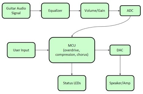
During the development of our pedal board it will be necessary to use the RS-232 standard in debugging our code. Most people are familiar with the RS-232 standard for serial ports on computers. In our implementation of the standard, we will be using 3 wires: one for transmission, one for receiving, and one for ground. This enables us to easily send and receive data with the ATmega644’s USART (Universal Asynchronous Receiver/Transmitter) interface after stepping up the voltage to +5 and -10 volts so that it can interface with the computer’s serial port.
guitar, atmega644
Our project will be implementing the Serial Peripherial Interface Bus (SPI) from Motorola to communicate with the external ADC and DAC. SPI consists of four wires as follows: Serial Clock (SCLK), Serial Data Out (SDO), Serial Data In (SDI), and Chip Select. The use of both an output and input wire enables devices to operate in full duplex mode. In practice the “master” will set its CS low to the desired “slave,” and output a clock signal on SCLK and data on SDO. The slave is also free to send back data over the master’s SDI while CS is low.
Code-wise, the C source code of our project will conform to the ANSI C standard put in place by the American National Standards Institute.
Parts List:
|
Part |
Part Number |
Quantity |
Unit Cost |
Total Cost |
Vendor |
|
| Complete Prototype Board | ECE 4760 v7/2008 | 1 | Free | Free | Donated | |
| Microcontroller | ATmega644P | 1 | Free | Free | Donated | |
| Solder Boards | 3 | $2.50 | $7.50 | ECE 4760 Lab | ||
| Analog to Digital Converter | AD7680 | 1 | Sampled | Sampled | Analog Devices | |
| Digital to Analog Converter | LTC1657 | 1 | Sampled | Sampled | Linear Technologies | |
| 12 Volt Power Supply | 1 | $5.00 | $5.00 | ECE 4760 Lab | ||
| 5 Volt Power Supply | EPS050100-P5RP | 1 | $8.06 | $8.06 | Digikey | |
| -5 Volt Voltage Converter | ICL7660 | 1 | $1.82 | $1.82 | Digikey | |
| 2.1mm Power Jack | PJ-002A | 1 | $0.80 | $0.80 | Digikey | |
| 1K Resistor | 6 | $0.00 | $0.00 | ECE 4760 Lab | ||
| 5.1K Resistor | 27 | $0.00 | $0.00 | ECE 4760 Lab | ||
| 3K Resistor | 2 | $0.00 | $0.00 | ECE 4760 Lab | ||
| 100K Resistor | 2 | $0.00 | $0.00 | ECE 4760 Lab | ||
| 2.2 nF Capacitor | 9 | $0.00 | $0.00 | ECE 4760 Lab | ||
| 10 nF Capacitor | 4 | $0.00 | $0.00 | ECE 4760 Lab | ||
| 20 nF Capacitor | 11 | $0.00 | $0.00 | ECE 4760 Lab | ||
| 50 nF Capacitor | 2 | $0.00 | $0.00 | ECE 4760 Lab | ||
| 0.1 uF Capacitor | 21 | $0.00 | $0.00 | ECE 4760 Lab | ||
| 10 uF Capacitor | 2 | $0.00 | $0.00 | ECE 4760 Lab | ||
| Dual Operational Amplifier | LM358AN | 9 | $0.00 | $0.00 | ECE 4760 Lab | |
| Green LED | 3 | $0.00 | $0.00 | ECE 4760 Lab | ||
| Red LED | 1 | $0.00 | $0.00 | ECE 4760 Lab | ||
| Wire | lots | $0.00 | $0.00 | ECE 4760 Lab | ||
| Potentiometer (with knob) | LP-10KC | 1 | $0.80 | $0.80 | All Electronics | |
| Sliders | SLP-100KA | 7 | $0.80 | $5.60 | All Electronics | |
| Arcade Switches | LPS-2A | 3 | $4.35 | $13.05 | All Electronics | |
| Wood | 7 panels | $0.97 | $6.79 | Katom Restaurat Supply | ||
|
Total Cost of Project: |
$49.42 | |||||
For more detail: Compact Guitar Pedalboard Using Atmega644