1 Introduction
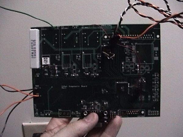
Our final project is the CUSat Diagnostic Board (CUDB). This board will be used for monitoring CUSat system health as well as performing various functions allowing for easy integration and debugging of CUSat components.
1.1 CUSat
CUSat is the Cornell satellite team’s entry into the Nanosat-4 competition sponsored by the Air Force Research Labs (AFRL). A significant milestone for CUSat is entering the “flat-sat” stage of manufacturing. This is where all satellite components are electrically connected on a clean-room bench, but not structurally integrated into the satellite frame. To make flat-sat debugging and integration easier, we have developed the idea of the CUSat Diagnostic Board (CUDB).
1.2 Report Layout
This project involves the combination of many circuit systems and many software systems. We have split up the report into several sections. Sections 3 and 4 of this report contain only design details. They do not contain the results of our tests and experiments to verify the functionality of the CUDB. Section 5 details our results of testing the various systems. Section 6 contains our conclusions.
2 CUDB Design Overview
The CUDB has the following functionality (each one of these functions is discussed in detail later in this report):
- Current sensing of the CUSat power bus
- Charge and discharge the CUSat batteries
- Supply CUSat with a source of power
- Ability to reprogram all microcontrollers on the satellite without have them removed from flat-sat
- Interface with a PC for human control and data observation
The design of the CUDB is such that we can “make life easier” for the other subsystems as they begin integrating their hardware into flat-sat. For example, the first subsystem to have hardware in flat-sat is the Power subsytem. The Power subsystem harnesses energy from solar cells, which will not operate while we are in lab. As such, the CUDB provides the 18.5 volts that the Power subsystem expects from the solar cells – letting the Power team test their hardware. Further, the Power subsystem has a battery charging circuit which CUDB can power. And, CUDB provides a method of discharging the batteries (normally done by running actual CUSat hardware in flat-sat).
For the reasons outlined above, the only way for CUSat to complete a finished product with the project’s strict schedule is to have the CUDB operational by the time flat-sat is fully developed.
Most of the part selection has been completed by CUSat members Kris Young and Michael Austin. The basic PCB design was finalized by CUSat member Tyler Orchowski, and reviewed by Eric Brumer & Jiangang Shi. Our project entails:
- Populating and testing the CUDB as a standalone device
- Writing all of the CUDB software (MCU and the graphical user interface [GUI])
- Interfacing the CUDB with:
- CUSat subsystem hardware
- CUSat data bus
- CUSat batteries and power subsystem
- The CUDB GUI
2.1 Specifications
Since CUSat is being developed for the AFRL, all components (including support equipment such as the CUDB) must comply with select military specifications (MIL-SPECs). Here are some specifications which must be followed for CUDB development:
- MIL-STD-1540D – “Product Verification Requirements for Launch, Upper Stage, and Space Vehicles”
- KHB 1700.7C – “Space Shuttle Payload Ground Safety Handbook”
- DOD-W-83575A – “General Information for Wiring Harness, Space Vehicle, Design and Testing”
A complete list of the military and department of defense specifications is not available to be published due to International Trade and Arms Regulations (ITAR) restrictions. However, if the reader is interested in mil-specs, please contact Eric Brumer for more information.
2.2 Parts List
- Custom 2-layer Printed Circuit Board (PCB)
- Atmel Mega128
- 16MHz Crystal
- LM3480IM3-5.0 18.5V, 5V Voltage Regulator
- LM4040 Zener diode voltage shunt
- MAX3083, RS-485 Driver
- MAX3322, RS-232 Driver
- MAX4372T, Current Sense Amplifier (3x)
- MIC442A, Power FET Drivers (5x)
- Si4410DY, FET Switch (5x)
- 1101M2S3CQE2, Mechanical on/off switch
- 808 Circuit Breaker (3x)
- AD7376-10k, High precision digital potentiometer
- Various capacitors, resistors and resistor packs
- Various LEDS for debugging and display information
We would like to petition that we lift the cost constraint, as the CUDB shall be used for a Cornell project team.
3 CUDB Hardware Design
3.1 Current Sensing
It is required that all power lines be monitored (current and voltage) in CUSat at all times. This is for the safety of all components on the satellite, and for the safety of the CUSat members working on flat-sat. Current sensing will be accomplished with the MAX4372T sense amplifier with a FET driver chip (MIC442A) and a FET switch (Si4410DY), as depicted in the following battery discharge circuit:
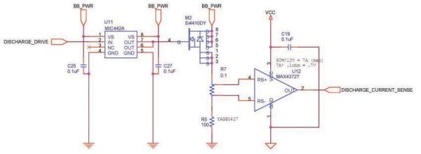
The battery discharge circuit (shown above) works as follows. PORT C2 on the MCU (labeled DISCHARGE_DRIVE) is input to a MIC442A driver chip. The FET driver chip is used for one main reason:
- In the event of a circuit malfunction, it is possible that the battery discharge current will enter the MCU pin, most likely destroying the pin or the entire MCU. With the driver chip in place, we isolate the MCU from the battery charging circuit so problems with the battery charging circuit will not affect the MCU.
The output of the MIC442A is fed into a FET switch (Si4410DY), which controls whether or not the batteries (at VBATT = 12V) are discharged through a 100 ohm power resistor (labeled R5 in the above diagram).
If the Si4410DY is closed, the discharge current passes through a 0.1 ohm resistor (labeled R7) which is used for current sensing. The current sensing input is fed into a MAX4372T (current sense amplifier with a gain of 20). The maximum draw the CUSat batteries can produce is 7A (=80W max / 12V bus), which is well above any currents which will be seen by the 0.1 ohm or 100 ohm resistor. With a 12V bus, the total current drop through 100.1 ohms of resistance is 120mA, which is the expected current to be measured by the MCU.
Since the output of the MAX4372T is fed into PORTF on the MCU, it is worthwhile to mention how we interpret ADC readings for current sensing at this time. The AREF pin on the MCU is set to a very stable 4.1V (circuit described later). Thus, if the ADC reading read 4.1V as the output of the MAX4372, that corresponds to a voltage drop of 4.1 / 20 = 0.205V across the 0.1 ohm resistor. This corresponds to a current of I = V / R = 2.05A. And, if the voltage read by the ADC was 0V, this corresponds to a current passing through the 0.1 ohm resistor of 0A.
Since we use the top 8 bits of the ADC as a measure of the current passing through the 0.1 ohm resistor, a read value of 255 corresponds to a discharge current of 2.05A, and a read value of 0 corresponds to a current of 0A. Therefore, to get the discharge current we simply multiply the read value by 2.05/255 = 0.008.
The second current sensor is used for measuring current while charging the batteries. PORT C0 of the MCU is input to a FET driver chip and a FET switch exactly as before. Here, however, when the FET switch is activated, +18.5V from the power supply is supplied to the batteries to charge them.
The last current sensor is used for measuring current supplied to the satellite power bus, and employs the same circuitry as described above.
All of our ADC measurements are with respect to an external AREF. We use an LM4040 4.1 (voltage shunt/zener diode) to provide a very stable 4.1V AREF.
3.2 Battery Charging and Discharging
Battery charging and discharging is done in conjunction with two of the three current sensing circuits (charge and discharge), and the CUSat power subsystem components. The CUSat power board (as well as the batteries being used) will not be discussed in this report, but it employs two algorithms (run on a separate microcontroller) to determine when the batteries have finished charging or discharging. For the CUDB alone, this will be done through manual inspection of the CUDB outputs using a multimeter. The battery voltage is run to the MCU through a connector to the batteries, labeled VBAT_SENSE in the schematic.
Battery charging is a complicated task in of its own, and we do not present the details of how CUSat performs charging and discharging. However, if CHARGE_DRIVE is asserted by the CUDB MCU, then 18.5V is supplied to the power subsystem. For testing purposes, we verify this using a multimeter. If DISCHARGE_DRIVE is asserted by the CUDB MCU, then a power supply (simulating the batteries) will source current through the 100 ohm resistor described earlier. This way, we can test the full functionality of the ADCs before we integrate the CUDB with the CUSat Power subsystem.
3.3 Serial Communication Driver Chips
The CUSat data bus employs RS-485 serial communication. This is differential, bus based serial communications, where the difference on two wires is used to indicate logic 1 or logic 0. If the difference between the two RS-485 wires is greater than 200mV, it is logic 1. And if the difference between the wires is less than -200mV, it is a logic 0.
Here, SAT_RX and SAT_TX are TTL outputs of the CUDB MCU, which get converted to RxA, RxB (two differential receive lines), and TxA and TxB (two differential transmit lines). The two capacitors are bypass capacitors for the driver chip.
The two 1k resistors (R15 and R16) are to allow for microcontroller reprogramming. Section 4 of Atmel Application Note AVR042 states that in order to reprogram an Atmel MCU using SPI we cannot drive ports E0 and E1. However, in our circuit, we are driving those pins; we connect E0 and E1 to the MAX3083 driver chip (E0 = SAT_RX, E1 = SAT_RX) as UART0. In order to allow for reprogramming, the application note suggests inserting 1k resistors between E0 and E1 their corresponding driving inputs. This is a serious issue, and it is unfortunate that Atmel has this information tucked away in an application note instead of in the Mega128 documentation.
Note that SAT_RE and SAT_DE are the receive and transmit enable (respectively) of the RS485 driver chip, and are MCU controlled (SAT_RE = PORT C5, SAT_DE = PORT C6).
The CUDB must communicate with RS-232 on a PC: we use the MAX3322 driver chip to turn the MCU’s UART1 port to RS-232 compatible levels.
3.4 CUSat Inhibits
One of the requirements for all satellites to be launched into space via an Air Force launch vehicle is that solenoid-based electromechanical safety inhibits be in place between all power supplies (batteries & solar cells) and their loads (subsystems). This is to ensure (mechanically) that the batteries do not supply power to the rest of the satellite before the satellite has been ejected from the launch vehicle (ie: the satellite doesn’t turn on while it is being launched into space).
The inhibits which will be in place on CUSat require +/- 12V to operate. The CUDB will provide this voltage through a series of switches and regulators and software controlled. The final inhibit signal is labeled INHIBIT.
The following schematic contains our implementation of the INHIBIT generation scheme. PORT G0 (INHIBIT_DRIVE_POS) from the MCU is connected to a FET driver / FET switch like in the current sensing circuitry. PORT G1 (INHIBIT_DRIVE_NEG) from the MCU has a similar setup.
G0 is the positive inhibit driver: if it is asserted, then INHIBIT is connected to the CUDB power source (a power supply for the CUDB, but it will be the solar cell array and batteries on the complete CUSat). If G1 is asserted, then the +12V power source is brought to a TI-059 regulator which transforms this +12V signal to a -12V signal, then fed to the INHIBIT line.
Parts List:
- Custom 2-layer Printed Circuit Board (PCB)
- Atmel Mega128
- 16MHz Crystal
- LM3480IM3-5.0 18.5V, 5V Voltage Regulator
- LM4040 Zener diode voltage shunt
- MAX3083, RS-485 Driver
- MAX3322, RS-232 Driver
- MAX4372T, Current Sense Amplifier (3x)
- MIC442A, Power FET Drivers (5x)
- Si4410DY, FET Switch (5x)
- 1101M2S3CQE2, Mechanical on/off switch
- 808 Circuit Breaker (3x)
- AD7376-10k, High precision digital potentiometer
- Various capacitors, resistors and resistor packs
- Various LEDS for debugging and display information
For more detail: CUsat diagnostic board using Atmel mega32