In this Instructable, I cover modding the store-bought Deluxe Identity Disc to an upgraded version with 64 leds, controlled by an AVR MCU. The upgraded version is costume-ready and would be an excellent addition to your Tron costume – it’ll also look great on your desk/dresser/etc.
My 7 year old daughter watched Tron:Legacy with me on Father’s day and decided instantly that she wanted to be Quorra for Halloween. I knew the costume would be a decent bit of work, and I don’t sew (although I will be getting assistance making the costume – hopefully a forthcoming instructable) – I decided to start with the Identity Disc.
I managed to find an identity disc at Target for $9 on clearance (they can be found on Amazon for $12 as of the writing of this article). However, when we brought the disc home, I was seriously disappointed at the lack lighting. So – like any good father would do – I set out to upgrade the disc.
Please note that this project does not preserve the original sound – I’d really like to include something, but didn’t find any AVR examples I really liked. If you have any suggestions for sound inclusion – please share!
Before I start the article – and before people say they can’t do this themselves – let me be clear about my qualifications. I’m a Software Developer (.Net). I’m not an electrical engineer, my soldering skills are sub-par, and even though I’m a developer – my AVR code is probably horrible. If I can do it, anybody with a lot of patience and time can as well.
And take it easy on me – this is my first Instructable!
When I started my research – I ran across this article: Tron-Disc-with-NET-Microframework. Fantastic implementation – all LEDs can be controlled individually, adjustable brightness. Then I noticed the huge board in the middle. And the expensive cost of the hardware, etc. I needed something that wouldn’t break the bank, and parts that I could fit in the disc.
But first – let me leave you with a little teaser video. This is what the device looks like with the V1
Step 1: Materials & Tools
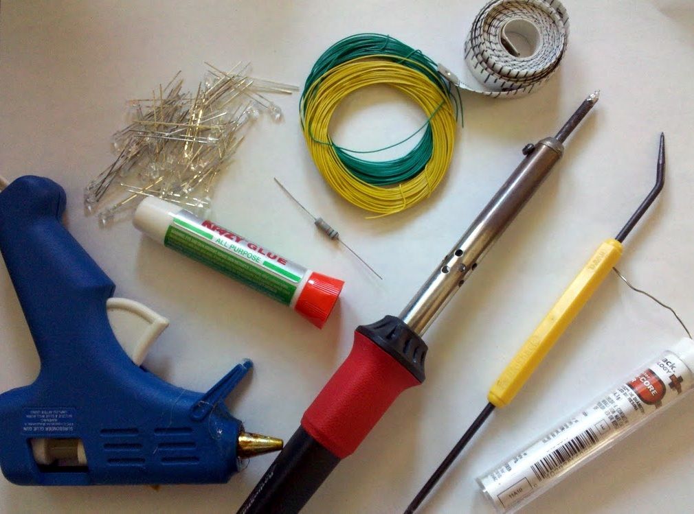
Materials:
• Tron Deluxe Identity Disc
• 3 x AAA alkaline batteries – any battery source between 4 and 5.5v would work, but you’re limited on space
• 64 LEDs (I bought a set of 100 blue on Ebay for $3.50 including shipping)
• ATMega328/168 or ATTiny45- I was able to get free samples from Atmel – warning – they’re much more difficult to obtain than Maxim
Any AVR chip that supports SPI/USI and has an additional 2 input pins would probably work as well
• Max7221 or Max7219 LED Display Driver – I was able to get free samples from Maxim – they provide samples fairly freely
I have not tested with the Max7219 – but from what I’ve seen online, these should be interchangeable
• 50+ feet of 30awg wire – seems like a lot – but you’ll need it
• RSet Resistor – I needed a 15k resistor – this helps the LED Driver determine what current/voltage to use
See this page for more information on values
• Solder (I suggest something small like 0.032)
• Perfboard – a small sheet is all you’ll need.
You’ll want the kind with the copper rings. Veroboard would probably work as well, but it’s more expensive
• 24 pin DIP IC Socket (Optional – used for the Max7221 – I don’t trust myself to not fry the IC)
• 28 pin DIP IC Socket
• Two pens with springs
• Hot Glue Sticks
• cyanoacrylate
• Magnetic Reed Switch – I used the glass kind
For the second disc, I used a COTO-20 I purchased from eBay. For the first disc, I harvested one from a broken child’s toy
Tools:
Soldering Iron – I’m not using anything fancy – just an $8 iron from RadioShack
Soldering Helper – Not sure what it’s really called, but it comes with the RS Iron – it’s a thin tool that I used to help route wires, wrap wire, etc. It proved invaluable. This or a similar tool will come in handy.
Dremel, cut off disc and engraving tip (Optional, but highly suggested)
Wire cutters
Wire stripper (Optional – finger nails work very well on 30awg)
AVR Programmer – I use a $6 USBASP programmer I found on eBay
Silver Sharpie (Optional)
Hot Glue Gun
Pliers – ideally a small pair
Step 2: Gut it!
BEFORE YOU START – Get yourself a zip-top bag. You’ll probably want to save all of the original parts. If you want to expand on my design, some of the extra pieces might come in handy.
OPEN IT UP
Dis-assembly is fairly simple. Start with the six screws on the back and the battery compartment to open. The rest of the process should go fairly quickly. No prying should be necessary. Remove the batteries as well.
(See Picture 1)
REMOVE THE ELECTRONICS
Take out all of the electronic components from inside the disc. There is some masking tape you’ll have to take off to get some parts out.
Use your wire cutters to disconnect the electronics from the Battery compartment.
(Pictures 2-5)
KNOW WHAT YOU’LL BE REMOVING
We’ll be removing a lot of extra plastic to make room for our new components. To avoid removing something you shouldn’t, I suggest marking the posts you’re keeping to avoid confusion.
(See Picture 5)
Step 3: Prep the shell – Part 1
BATTERY COMPARTMENT
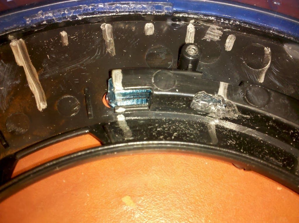
For this project, I wanted the AVR chip to be accessible in case I wanted to upgrade the code without taking the disc apart. We need to remove most of the battery compartment while leaving the edge so that the original cover will still fit nicely.
Start by removing the flat piece on top (See Picture 1). You’ll notice the melted areas – these can be broken off fairly easily to expose the pieces we’ll be removing. Make sure to save the metal clips from the compartment – we’ll need those later. See Picture 2 for how the compartment looks like after the top piece and clips have been removed.
Once you’ve removed the clips – this is where the Dremel really comes in handy. You need to leave the screw post, the two holes where the tabs from the battery cover goes and enough of an edge for the cover to sit on (See Picture 3)
START CUTTING
There are two ways you can go about this. You can start with a cutting wheel or sander on your Dremel and get rid of all the extra fins, posts, etc. I prefer to cut as much as I can with my wire cutters and then use the Dremel to smooth everything out. Don’t have a Dremel? It’ll make it easier, but it doesn’t have to be perfectly smooth. A hobby knife might work to get rid of the last bits as well. Again, make sure not to cut off any of the posts that we need to save.
See picture 2 for what the disc looks like after cutting of the tabs, etc with a wire cutter. You can smooth the roughness with the edge of a cutting disc.
Note – this step doesn’t have to be perfect. We’re doing most of our work on the top half of the shell. We’re removing the tabs, etc from the bottom to provide extra clearance.
BLADE
This step is fairly simple. Using a sharp knife or wire cutters, remove all tabs from the blade. That’s it! See picture 4 for what the blade looks like.
Step 4: Prep the shell – Part 2
GLUE THE BLADE
We’re gluing the blade to the top half of the Disc – this is the half with the clear C-ring. Do not glue it to the bottom!
Because we’ve removed the guides and tabs that helped put the blade in place – I recommend putting the blade back in. Once you’ve done that – make sure two halves can close fully. Once you’ve checked to make sure you’ve inserted the blade correctly, remove the bottom half and run a bead of superglue around the inside of the blade where it meets the black plastic. We’re mostly doing this so that it will stay in place while we’re fitting in our electronics – don’t go crazy with the glue.
MARKING THE DISC
In order to make the new disc as movie-accurate as possible, we’re placing 16 leds in the inner ring (convenient since the LED chip we’re using breaks leds into segments of 8). The remaining 48 leds will go on the outer ring.
I found that the inner ring is about 40cm and we need 15 breaks – leaving 2 2/3 cm between each LED. I mostly eyeballed this section, but used a measuring tap used for clothing measurements to make things a little easier.
The outer ring is much simpler. We need to separate it into 48 segments. There are already 6 posts evenly spaced around the disc. Using your sharpie, make a large mark at each of these posts (6 marks). Then add a large mark in the middle of each post (12 marks). Then make a smaller mark between each of the large marks (24 marks). Then add a smaller mark between all of the marks (48 marks!).
OPENINGS FOR THE INNER LEDS
On the inside of the inner ring, you’ll need to make openings in the black plastic so that each LED can shine through. I like to use an engraving tip on my dremel to make these openings. A small sanding drum would probably work as well.
Using one of your LEDs, make sure you have a large enough opening so that the LED will shine through at each location.
For more detail: Custom Tron Disc Mod using ATMega328


