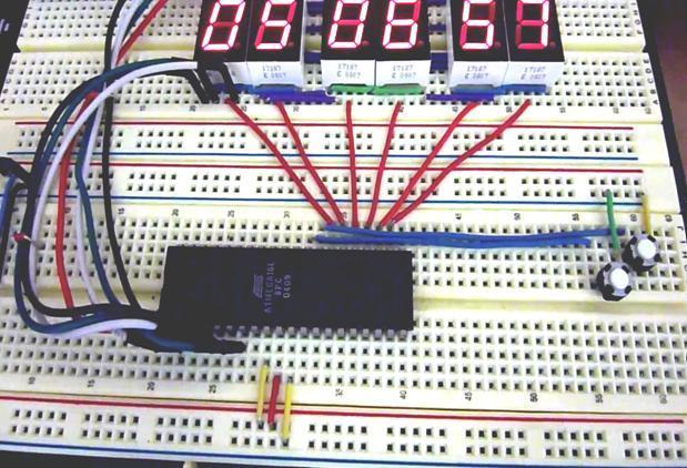
In this ATMega16 AVR project we will be designing and implementing a digital clock with the aid of a atmel AVR ATMega16 microcontroller and seven segment display. Before going through this digital clock AVR project it is recommended to complete the tutorial on Interfacing a Seven Segment Display with the AVR Microcontroller.
Note: Although this AVR project was designed around the ATMega16 the project could have utilized another microcontroller such as an ATMega32, ATMega8515, etc.
ATMega16 Digital Clock Operation
Our digital clock operates as follows. When the circuit is powered up the clock starts at “00:00:00” for “HH:MM:SS”. There are two push-button switches used to set the time. Switch SW1 is for setting the minutes, when this button is pressed the minutes in increase until it reaches 59 then reset and start counting from 0. Switch SW2 is for setting thehours.
One feature to note in that all seven segment displays are driven by the same port (PortB). The microcontroller through controls from PortC indicate which seven segment display each digit is displayed on. Note that these Seven Segment Displays are common cathode display. In order for our digital clock to work correctly the internal oscillator of the ATMega16 AVR microcontroller must be enabled and set to 4MHz
Project Source Code
###


#define F_CPU 4000000UL
#include <avr/delay.h>
#include <avr/io.h>
#include <avr/interrupt.h>
#define SegDataPort PORTB
#define SegDataPin PINB
#define SegDataDDR DDRB
#define SegCntrlPort PORTC
#define SegCntrlPin PINC
#define SegCntrlDDR DDRC
/*Global Variables Declarations*/
unsigned char hours = 0;
unsigned char minutes = 0;
unsigned char seconds = 0;
/*Function Declarations*/
/*****************************************************************************/
/*Decimal Digit (0-9) to Seven Segment Values Encoder*/
unsigned char DigitTo7SegEncoder(unsigned char digit, unsigned char common);
/*Timer Counter 1 Compare Match A Interrupt Service Routine/Interrupt Handler*/
ISR(TIMER1_COMPA_vect);
/*Main Program*/
/*****************************************************************************/
int main(void)
{
    SegDataDDR = 0xFF;
SegCntrlDDR = 0x3F;
SegCntrlPort = 0xFF;
TCCR1B = (1<<CS12|1<<WGM12);
OCR1A = 15625-1;
TIMSK = 1<<OCIE1A;
sei();
while(1)
    {
        /* Set Minutes when SegCntrl Pin 6 Switch is Pressed*/
if((SegCntrlPin & 0x40) == 0 )
{
_delay_ms(200);
if(minutes < 59)
minutes++;
else
minutes = 0;
}
        /* Set Hours when SegCntrl Pin 7 Switch is Pressed*/
if((SegCntrlPin & 0x80) == 0 )
{
_delay_ms(200);
if(hours < 23)
hours++;
else
hours = 0;
}
SegDataPort = DigitTo7SegEncoder(seconds%10,1);
SegCntrlPort = ~0x01;
SegDataPort = DigitTo7SegEncoder(seconds/10,1);
SegCntrlPort = ~0x02;
SegDataPort = DigitTo7SegEncoder(minutes%10,1);
SegCntrlPort = ~0x04;
SegDataPort = DigitTo7SegEncoder(minutes/10,1);
SegCntrlPort = ~0x08;
SegDataPort = DigitTo7SegEncoder(hours%10,1);
SegCntrlPort = ~0x10;
SegDataPort = DigitTo7SegEncoder(hours/10,1);
SegCntrlPort = ~0x20;
    }
return 0;
}
/*
* Function Description:
* Encode a Decimal Digit 0-9 to its Seven Segment Equivalent.
*
* Function Arguments:
* digit - Decimal Digit to be Encoded
* common - Common Anode (0), Common Cathode(1)
* SegVal - Encoded Seven Segment Value
*
* Connections:
* Encoded SegVal is return in the other G-F-E-D-C-B-A that is A is the least
* significant bit (bit 0) and G bit 6.
*/
unsigned char DigitTo7SegEncoder(unsigned char digit, unsigned char common)
{
unsigned char SegVal;
switch(digit)
{
case 0: if(common == 1) SegVal = 0b00111111;
else SegVal = ~0b00111111;
break;
case 1: if(common == 1) SegVal = 0b00000110;
else SegVal = ~0b00000110;
break;
case 2: if(common == 1) SegVal = 0b01011011;
else SegVal = ~0b01011011;
break;
case 3: if(common == 1) SegVal = 0b01001111;
else SegVal = ~0b01001111;
break;
case 4: if(common == 1) SegVal = 0b01100110;
else SegVal = ~0b01100110;
break;
case 5: if(common == 1) SegVal = 0b01101101;
else SegVal = ~0b01101101;
break;
case 6: if(common == 1) SegVal = 0b01111101;
else SegVal = ~0b01111101;
break;
case 7: if(common == 1) SegVal = 0b00000111;
else SegVal = ~0b00000111;
break;
case 8: if(common == 1) SegVal = 0b01111111;
else SegVal = ~0b01111111;
break;
case 9: if(common == 1) SegVal = 0b01101111;
else SegVal = ~0b01101111;
}
return SegVal;
}
/*Timer Counter 1 Compare Match A Interrupt Service Routine/Interrupt Handler*/
ISR(TIMER1_COMPA_vect)
{
seconds++;
if(seconds == 60)
{
seconds = 0;
minutes++;
}
if(minutes == 60)
{
minutes = 0;
hours++;
}
if(hours > 23)
hours = 0;
}
###
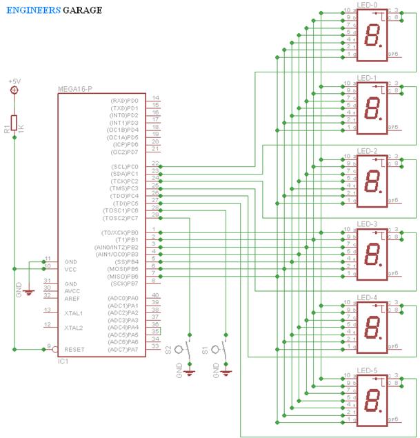
Circuit Diagrams
For more detail: Digital Clock using Seven Segment Display and ATMega16