Introduction
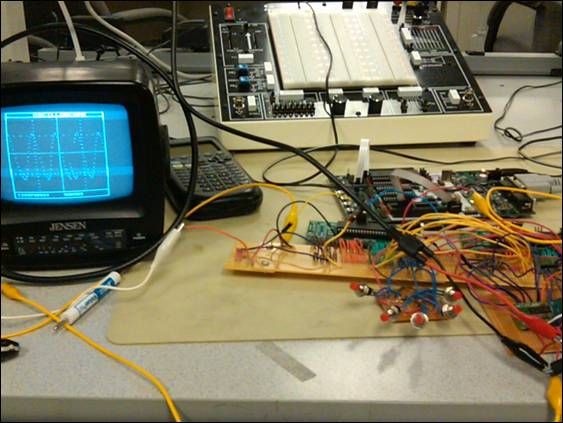
The goal of our project is to design a digital oscilloscope with 20 kHz bandwidth. The scopes that we use in ECE 4760 lab cost over one thousand dollars. The motivation of our project is to produce an affordable, easy to make oscilloscope for students or other engineers who cannot afford to buy a manufacturers oscilloscope. We are aiming for a range of up to 20 kHz and the waveform is displayed on a 5 inch black and white television. Two microcontrollers are used to store and print data onto the screen.
High Level Design
Oscilloscopes are very versatile pieces of electronic test equipment that are used in a wide variety of applications. For example, heart beat patterns can be displayed on a specialized type of oscilloscope called an electrocardiogram. With all these uses, we decided that it would be interesting to build our own 200 kHz digital oscilloscope. This project presents difficulty in both hardware and software design. Having a solid understanding of how this tool works will be essential for our future as electrical engineers.
Background Math
This project relies on sampling a waveform and then reconstructing it. The Shannon sampling theorem, which states that samples must be taken at a rate greater than twice the maximum frequency of the original signal (or at the Nyquist rate), is used so that no aliasing occurs. Aliasing occurs when a signal gets undersampled; a waveform of lower frequency will get reconstructed instead of the correct higher frequency signal. A picture is shown below to illustrate the idea:
The undersampled waveform will have a frequency of:
falias = fsample-rate foriginal-signal
Therefore, in this project, the sampling rate is always set higher than 40 kHz (the oscilloscope functions correctly at a maximum frequency of 20 kHz). The A-to-D converter is responsible for sampling and has a maximum sampling rate of 2 megasamples/sec.
Logical Structure
The analog circuits on our board simply adjust the amplitude and level of the input signal using standard op amp circuits. Depending on which time per div has been selected, MCU2 acquires data at a specific number of samples per second as determined by a timer. These samples are stored into the data buffer. Once it is filled no new data can be stored until all of the points in the buffer have been drawn.
Also depending on the time per div selected, MCU1 will request a certain number of data points per frame and draw these on the screen. For very high frequencies it will draw many points per frame to appear more ‘real time.’ Once MCU1 has drawn every point in the buffer MCU2 is free to start filling the buffer up again. This cycle continues indefinitely until the time per div is changed and the cycle then begins again.
Patent, Copyright and Trademark Concerns
The project uses some patented components as subcomponents. However, there is no patent limitation on our final design as we are using the devices as the manufacturer intended.
Hardware Design
Level Shifter and Amplifier
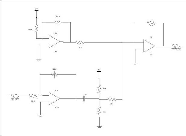
The signal to be displayed is applied to the 100k resistor of the lower op amp. The potentiometer can be adjusted to change the amplitude of the signal. The output goes into a capacitor to remove any DC level and the resistive divider sets a new DC level for the signal. The top op amp is designed to have an output from 0-5V. The two signals feed into a summing amplifier which adds the adjustable DC signal to the fixed level, variable gain input signal. The output of this op amp goes straight into the ADC.
Microcontroller Boards and Microcontrollers
Order to achieve our bandwidth goals for the oscilloscope we had to use two Atmel Mega644 microcontrollers. In order to use the microcontrollers without the STK500s we had to build the custom PC boards designed by Bruce Land for 4760. In addition to the microcontrollers, the hardware we used on the board was a DIP socket, six pin headers for the flash programmer, resistors and capacitors, a voltage regulator, an LED, and a 16 MHz crystal. We did not need serial communication for our project so we omitted the MAX233 and serial connection port.
Digital to Analog Converter
The video signal and sync signal were sent to the TV via port pins D.5 and D.6 respectively. A voltage of 0.3 V corresponded to a black pixel, while a voltage of approximately 1.1 V corresponded to a white pixel. The sync signal was a 0V signal. A sync pulse lasting 180 s signaled the start of a new frame, and a sync pulse lasting only 5 s signaled the start of a new line. We got the design for this DAC from ECE 4760 Lab 3.
Parts List:
|
Item |
Number |
Supplier |
Cost |
|
Custom PC Board |
2 |
4760 Lab |
$ 8.00 |
|
Mega644 |
2 |
4760 Lab |
$ 16.00 |
|
B/W TV |
1 |
4760 Lab |
$ 1.00 |
|
6 Inch Solder Board |
3 |
4760 Lab |
$ 7.50 |
|
2 Inch Solder board |
2 |
4760 Lab |
$ 2.00 |
|
Power Supply |
2 |
4760 Lab |
$ 10.00 |
|
DIP socket |
2 |
4760 Lab |
$ 1.00 |
|
Pin Headers |
40 |
4760 Lab |
$ 2.00 |
|
AD7825 |
1 |
Analog Devices |
$ – |
|
1 Pin Jumper Cables |
3 |
4760 Lab |
$ 4.00 |
|
Alligator Clips |
3 |
4760 Lab |
$ – |
|
SOIC Carrier Board |
1 |
4760 Lab |
$ 1.00 |
|
Op Amps (Not LM358) |
2 |
Digikey – National Semiconductor |
$ 5.66 |
|
Resistors/Capacitors/Push Buttons |
Many |
4760 Lab |
$ – |
|
Total Cost |
$ 58.16 |
For more detail: Digital Oscilloscope Using Atmega644