Summary
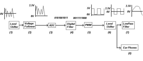
Our ECE476 Final Project is a digital pre-amplifier. A digital pre-amplifier basically takes an analog music signal, converts it digitally, and spits it out as a new, modified, analog signal. Our decision to do this project was sparked by our interest in music and electronic equipment. High-end receivers and amplifiers often use this analog to digital, digital back to analog conversion scheme along with Digital Signal Processing (DSP) to modify music signals. To understand, and possibly replicate how many high-end receivers work would be very exciting. Additionally, this project relates to a few of the design courses we have taken here at Cornell University, which include Power Switching circuits and DSP.
Digital Signal Processing
DSP is basically a substitute to analog filtering by using digital calculations sampled analog values. You can implement a digital filter using the following generic transfer function where n is the order of the filter and ‘b’ and ‘a’ are coefficients corresponding to the weights in the difference equation.
The above transfer function translates into the following equation for our music manipulation. In our calculation, S(t) is the sampled voltage. As an example, S(0) is the sampled voltage at the current time, S(-1) is the previously sampled voltage, S(-2) is the 2 sampled voltages prior etc. V(t) is the voltage output after digital filtering has been accomplished. Like S(t), we must also store these V(t) values since they will be used in future digital filter calculations. The equation below depicts a filter with an order of 2, but the equation can be expanded or contracted based on the filter order you are using.
It is easy to see that this is an Infinite Impulse response filter (IIR). An IIR filter takes previous inputs and outputs, and the current input, to calculate the new filtered output. As the name suggests, each new output is affected by an infinite amount of previous inputs (each input affects the next input, which affects the next input and so on).
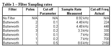
Finally, we obtained the coefficients for the transfer function using MatLab. We decided to use Butterworth type filters, which are know for their relatively flat pass and stop bands. Other filters we could have implemented include the Chebychev filters, which have a characteristically fast roll-off frequency but more ripple in the pass band or stop band. Using the MatLab command [b,a] = butter(2,0.2), we obtained the coefficients to our transfer function. The first parameter in ‘butter’ refers to the order of the filter; the second parameter indicates a cut-off frequency at defined certain percentage of the sampling frequency.
For more detail: Digital Preamplifier