Introduction
For our final project in ECE 4760, we designed and implemented a Reversi board consisting of hardware, a microcontroller, and a touch screen. Sixty-four bicolor (red and green) LEDs were implemented as the black and white pieces of the game. Players could simply light up a LED (place a piece) by touching the touch screen in the position right above the corresponding LED. Other LEDs would be flipped automatically according to the rules of Reversi, which is programmed into the microcontroller.

We designed this board for several reasons. We made this board an integration of board and pieces for the convenience to carry. And people will not be worrying of losing pieces when carrying the board around. Players do not necessarily have to find a flat platform to place the board because the pieces are free of tilting or sliding; players can easily move the board to anywhere else when needed, and resume the game right away. Additionally, players do not have to flip the pieces by themselves; instead, the micro-controller is in charge of that. Last but not least, people can play the game even in a completely dark area; there is no external light needed to play the game.
High Level Design
• Project idea – Rationale and Sources
Our idea of the final project was oriented by the desire to design something that would ultimately make life easier with the help of electronic products. So the product needed to be easy to access, intuitive to use, and feasible to be built based on what we had learned throughout the course.
We had come up with many interesting ideas derived from these criteria. But many of them were not implemented due to certain difficulties. The first one would have been a virtual mouse, which would have used a camera to capture the gesture of the hand to detect hand movement and hand gesture. But that would have involved too much images processing schemes, which might not be feasible for a 32-bit microcontroller to do. The second one would have been a LED umbrella, which would have told you the direction of the rains based on the intensity of the raindrops on the sectors of the umbrella. But raindrops would cause so limited tension on the sectors that we could not use a stretch sensor to detect that. And the surrounding noise was so high that we could not use a microphone to detect the sound of the raindrop. Our third idea, a calibrator of daily water drinking, was abandoned because it would be hard to calibrate the volume of water.
The idea of a digital Reversi board was triggered by the LED Cube project, which was built by previous ECE students from this course. We thought that LEDs were a good intermediary to reflect results because visual effects were direct to see, and intuitive to understand. In the same week, right before a regular club meeting, the club president asked Kai to play “Go” or “Connect Five”. And by coincidence, Kai was the representative of the day to deliver one Cornell Fact — “Fun Projects from ECE4760”. So we quickly met a consensus of a Reversi board design as our final project.
The design process took us several days especially the sensor interface. Bicolor LEDs were chosen to mimic pieces without doubts. But we needed a sensor interface which had to be precise enough to correctly light the corresponding LED, and physically feasible for a MCU to handle (a MCU only had 32 pins). Pushbuttons were simply not creative enough. Ideas like infrared sensor for each LED would cause false detection when lights were blocked, and would involve too much mechanical work; stretch sensor was not precise enough to measure touches at different locations. So we finally decided to use a touch screen, which would not be affected by any light effect, and was good enough to detect 64 different positions as a whole, and it only required 5 pins to get operated.
In addition to the Reversi board itself, we added two extra pushbuttons and one switch. The switch was for the power control. One pushbutton allowed the player to retract the last movement in case that there might be a false detection or an unwise movement. The other pushbutton was required by the rule to allow one player to yield the chance to the other player in the case that there was no further step to go.
• Mathematical Background
LED blinking frequency
As a MCU only had 32 controllable pins, it would be unfeasible to control all the LEDs separately. Inspired by the LED Cube, we designed in the way that there would be one row of LEDs connected to the ground each time to form complete a circuit. And the MCU would keep switching the rows fast enough simulate the same visual effect that turned-on LEDs would be always on. So we set the prescaler of the clock to be 2 (slow down the clock by 64 times), which was
16,000,000 Hz ÷ 64 = 250,000 Hz
The compare match interrupt service routine was trigger every 250 cycle, thus, the interrupt service routine has a frequency of 1,000 Hz. And the blinking task (task1) would be triggered every 20 interrupts occured. With 8 rows in total, each LEDs would have a frequency of
1,000 Hz ÷ 8 ÷ 20 = 6.25 Hz
In reality, task1 would be slowed down when other tasks got involved. So 6.25 Hz was a safe choice even if there would be other logics taken in place.
LED blinking frequency
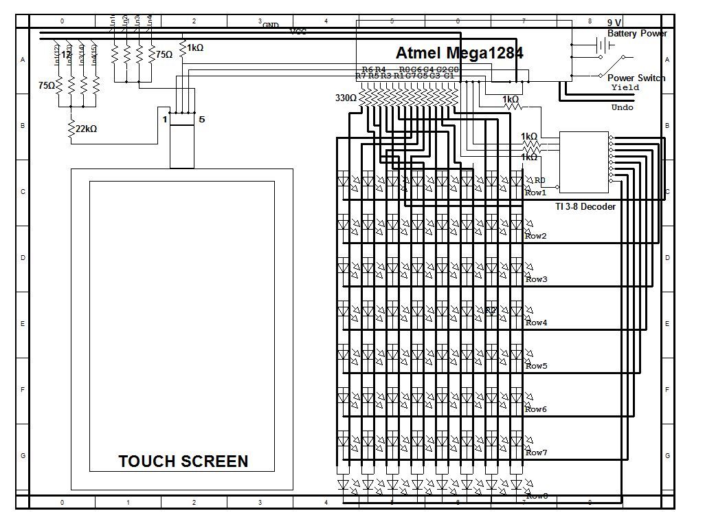
Pin assignment was one of the crucial parts of the design. The Atmel Mega1284 had 32 pins in total with 4 Ports — A B C and D. We planned to connect each row to the ground periodically while keeping columns sharing the same red cord and green cords. In this case, only one row would be powered because other rows would be open circuits. We also used the 8 pins in Port C for the 8 columns of green LEDs signal, and the 8 pins in Port D for the 8 columns of red LEDs. A complete soldered model was shown above.
With the fix cost of 16 pins, we could not afford another 8 pins for the row switching, or that would have left us so limited pins for touch screen connections. A 3-to-8 decoder in this case solved our problem sharply. So A5 – A7 were assigned to the decoder pins. The signal from the touch screen goes directly to the A0 pin. B6 and B7 were used to enable the X and Y coordinates detection on the touch screen so we would get an X coordinate and a Y coordinate separately. And lastly, B1 and B2 were used for the pushbuttons. Other port pins were left unconnected. So we used in total 24 pins out of 32 controllable pins. Port Vcc and GND were also used.
16 (LED Power) + 3 (Decoder) + 2 (Touch Screen Enable) + 1 (Touch Screen Signal) + 1 (yield button) + 1 (retract button) = 24Pins
• Logical Structure
There were three parts constituted the majority of the system. They were the MCU, the touch screen, and the LED board. The resistive touch screen was the sensor interface used to sense any touch on the screen, and then output the signal to the MCU.
The MCU then acted like a terminal, which received the signal from the touch screen, and then converted that to digital signals by using Analog to Digital Conversion (ADC). After checking for de-bounce, it then compared the digital value to the pre-set position value to find the corresponding LED that needed to be turned on. The MCU was also responsible to check whether the player was allowed to turn on the pointed LED according to Reversi rules. Every time a new LED was turned on, the MCU would check whether LEDs on the same row or column needed to be flipped according to the rule. If the player pushed the retract button externally, the MCU should react accordingly. The MCU would check which player won by comparing the number of green LEDs and red LEDs. But to trigger the winner check, two consecutive push of the “yield” button was required – both of the players thought there were no other steps they could go. The MCU was also responsible to close and open different rows’ circuit each time so that the LEDs could get displayed properly.
The LED board was a regular 8-by-8 Reversi board setup. Although the 8 columns were sharing the same Port C and Port D, there would be only one row connected to ground each time. So we had different buffers for different rows according to row number that the decoder was choosing.
• High Level Design Block
• Hardware/Software Tradeoffs
Hardware
Our goal of this project was to provide an intuitive to play and convenient to use product. So we made everything into one box with layer structure where players could only see the LEDs and the board matrix.
We separated the “yield” and “retract” button from the touch screen by placing them with the switch on the side. In this case, players would not be bothered when they were concentrating on the game. In the case that there might be a false detection which would light up the wrong LED, the “retract” button was required because pieces flipped on this digital Reversi board could not be physically retracted. The “yield” button was an indication to the MCU that a player was yielding the chance. And we used battery as the power source for the convenience to carry around.
We decided to use cardboard as the case instead of a steel one because cardboard was much lighter to carry with reliable solid structure.
We chose to connect rows to ground one by one because we could not afford enough pins on the MCU for individual LEDs. Constantly toggle the LEDs would shorten the LED life considerably but it was worth to do it.
Software
The benefit of having a digital Reversi board was that the system would flip the pieces for you by internal calculation. The system would also prevent players from placing the wrong position by simply not lighting the wrong LED even if the player touched the screen position above that. There would be a short delay after the finger touch the screen because of the Touch Screen Debouncing check. This was crucial for correct position detection.
We did not implement the winning check for two reasons. First, checking if there was a winner would involve too many logics, which might slow down other tasks. Second, players would know whether there was any other step they could take; if there was not, both of them would yield the chance. So two consecutive “yield” button pushes was a great external indication of the winning condition check. So the MCU could check the winner after receiving the indication.
We used Port.A and Port.B for both input and output purpose. But we had to declare them as input or output pins when we needed them to perform different functions. For example, we set Port.A as an input port when we wanted to read the signal from the touch screen. As a tradeoff we could not set the row selection. For the same reason, we set Port.B as an output in order to toggle the inputs to the touch screen. Meanwhile the system would be not able to detect external button pushes. The reason was that, pins of an outputting port could not perform in a desire way; we could not get any toggle signals if we put toggling pins and row selection pins all in Port.B.
• Relationship of your design to available IEEE, ISO, ANSI, DIN, and other standards
Due to our design, we did not implement things involved with any specific standard.
• Discuss existing patents, copyrights, and trademarks which are relevant to your project.
One patent we found similar to our design is a led board to play go (patent No.200920120062). Although the method to sense the position is different, there are several concepts overlapped and we do not believe there are any patent opportunity for our design. A further discussion was elaborated in the intellectual property section in Conclusion.
Parts List:
| Item | Vendor | Unit Cost | Quantity | Subtotal Cost |
|---|---|---|---|---|
| 9V Battery | ECE 4760 Lab | $2.50 | 1 | $2.50 |
| Atmel Mega1284 | ECE 4760 Lab | $5.00 | 1 | $5.00 |
| Bergquist 5-wire Resistive Touch Screen | Bergquist Co. P/N:BER251-ND, Sample | $0.00 | 1 | $0.00 |
| Bicolor LED, green and red, Through Hole | DigiKey, P/N160-1057-ND | $0.411 | 64 | $26.304 |
| Power Switch | ECE 4760 Lab | $0.00 | 1 | $0.00 |
| Red Push Button | ECE 4760 Lab | $0.00 | 2 | $0.00 |
| Small Solder Board(2”) | ECE 4760 Lab | $1.00 | 9 | $9.00 |
| Solder Board(6”) | ECE 4760 Lab | $2.50 | 1 | $2.50 |
| TI Line 3:8 Decoder, Through Hole | DigiKey, P/N:296-2091-5-ND | $1.31 | 1 | $1.31 |
| Total | $46.614 |
For more detail: Digital Reversi board using Atmega644