 Got some scavenged stepper motors from printers/disk drives/etc lying around?
Some probing with an ohmeter, followed by some simple driver code on your microprocessor and you’ll be stepping in style.
Step 1 Get to Know Steppers
Basically, you’re going to need to figure out where all the little wires go.
First step is to figure out if it’s a unipolar or bipolar motor. Have a look at Jones on Steppers for some deeper background, then at Ian Harries’ Site for a simple method to figure out an unknown motor.
Read up a bit, then join me in a walkthrough of this motor I got for cheap. (They’re on sale for $0.99 right now. They’re small, relatively light, but don’t have much torque. Don’t know what it’ll be good for yet.)
Step 2 Find Common Ground
So you’ve got five (or four, or six) wires. Your motor’s going to have two halves, and you can probably even tell just by looking which side each wire belongs to.
If you’re only looking at four wires, you’re in luck — it’s a bipolar motor. All you have to do is figure out which two pairs of wires go together.
If you’ve got a unipolar motor, or more than 4 wires, you’re going to have to break out your ohmeter. What you’re looking for is the common (ground) wire for each half. You can tell which is ground in a bipolar motor because it has half the resistance to either of the poles than the poles do across themselves.
Pictured is my notes from hooking up wires to wires and noting the resistance (or if they’re connected at all). You can see that White is the ground for the bottom trio b/c it has half the resistance to Red or Blue that they have to each other.
(This motor’s strange and doesn’t have a center tap on the top magnet coil. It’s like it’s half-bipolar, half-unipolar. Maybe you could use this to sense rotation in the Red-White-Blue coil when the Black-Yellow coil is being driven.)
Step 3 Figure out the Stepping Order
I was going to drive this motor as a bipolar one, so I’m ignoring the White ground wire. I’ve only got four wires to worry about.
You might want to run your unipolar motor as bipolar anyway, because it uses the whole coil in both phases instead of alternating between the two halves of each coil. More coil = more torque.
Run current through a pair (noting the polarity you chose) and then run current through the other pair at the same time. When you hook up the second pair, watch which way the motor turns. Write this down.
Now reverse the polarity on the first pair you chose. Then hook up the second pair again with their polarity also reversed. Note the direction.
From this you should be able to figure out the sequence for rotating the motor in either direction. In my example, both ended up turning counterclockwise, so stepping through the sequence in the same way I chose will step the motor CCW.
Step 4 Taking the Motor for a Test Drive

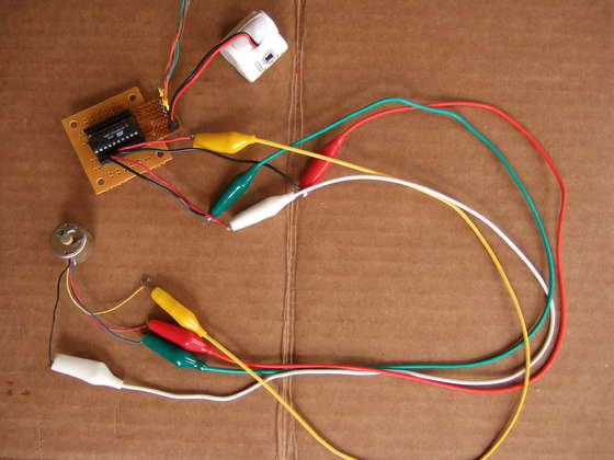
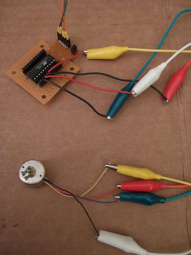
Hook up the wires directly up to your microproc and burn it up with the following code:
/* Playing with getting the small stepper motors driven. */
/* Include delay function */
#define F_CPU 1000000UL
#include
/* Pin defs for ATTiny2313 */
/* Clockwise order */
#define BLUE     _BV(PB0)
#define BLACK    _BV(PB1)
#define RED      _BV(PB2)
#define YELLOW   _BV(PB3)
#define DELAY  200 /* milliseconds between steps */
int main(void){
  DDRB = 0xff;    /* Enable output on all of the B pins */
  PORTB = 0x00;            /* Set them all to 0v */
  while(1){                     /* main loop here */
    PORTB = BLUE;
    _delay_ms(DELAY);
    PORTB = BLACK;
    _delay_ms(DELAY);
    PORTB = RED;
    _delay_ms(DELAY);
    PORTB = YELLOW;
   _delay_ms(DELAY);
   }
}
How simple is that code? Really simple.
All it does is make some nice definitions so I could refer to the wires by color rather than their pin-names, and then it toggles them on in sequence with an adjustable delay in between. For starters, I selected a half-second delay between steps.
See the short video for the results. If you’re really on your game, count the number of steps per cycle to figure out the motor’s single-stepping angular resolution.
For more Detail: Drive a Stepper Motor with an AVR Microprocessor using ATTiny2313 microcontroller
