Introduction
In the recent years, the MPEG Layer III (MP3) music compression format has become an extremely popular choice for digital audio compression. Its high compression ratio, and near CD quality sound make it a logical choice for storing and distributing music – especially over the internet, where space and bandwidth are important considerations. As a result of the MP3 popularity, a variety of portable MP3 players have entered into the market in an attempt to capitalize on the demand for portable, high quality music. In 1999, over 1.5 million portable MP3 players were sold worldwide and research projects the sale of over 30 million devices per year by 2005. We decided to design and implement a portable MP3 player similar to products currently available (e.g. Diamond Rio, Creative Labs Nomad, etc.).
Our goal was to design a scaled down version of an otherwise marketable product with minimal cost. Our intent was to ensure that our end result would be expandable to include all of the functionality of the most popular players on the market.
High Level Design
We used the ATMEL AT90S8535 microcontroller to control the components and data flow.
Our design supports standard MP3 file formats with a bitrate of 128Kbps. The decoder chip that we used supports rates from 8Kbps-320Kbps, but we decided it would be simpler to support one bitrate, and then expand the design to support other rates. Our decoder required the incoming bitstream to be equivalent to the decoded bitstream (128Kbps). Because our memory card has a memory latency of 1.5ms and the decoder has a 256-byte buffer – we decided to send data in 256 byte blocks.
At 128Kbps, 256 bytes will expire in 16ms, requiring a new data block. A major concern of this technique was buffer underrun/overrun. We prevented this by initially filling the buffer completely before starting to decode. Once running, a block is requested every 16ms, however the first request is sent approximately 8.5 ms after decode start to ensure that the buffer never contains more than 250 bytes and leaves us with just over 7ms to request and receive a block of data. These calculations are considered trivial and left as an exercise to the reader! 🙂
The pushbuttons are used to control the operation of the player. The four functions implemented with four buttons are play, stop, next track, previous track.
Program/Hardware Design
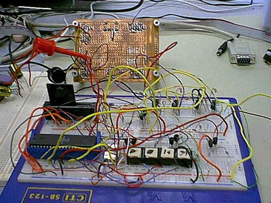
The parts used in this project were:
- ATMEL AT90S8535
- ST MicroElectronics STA013 (MP3 decoder)
- Crystal/Cirrus Logic CS4331 (18 bit serial DAC)
- SanDisk Multimedia Card (16MB serial flash card)
- 10 MHz crystal for decoder
- 4 MHz oscillator for MCU
- Function generator (replaceable by 11.2896MHz oscillator)
- resistors, capacitors, bipolar transistors, diodes, and connectors
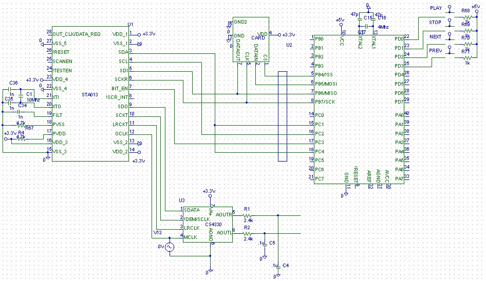
Schematic
Level shifting circuits
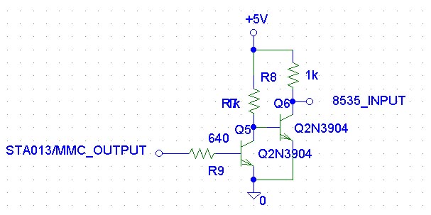
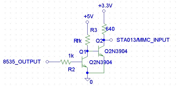
All the components used in the design are 3.3V except the ATMEL MCU that is 5V. As a result, every line that interfaced between the MCU and the other components needed to be level shifted. Lines that were unidirectional used the following circuits:
Step-up
Step-down
One line was bi-directional and used both the step-up and step-down circuits but were connected to two port pins on the MCU, one for input and one for output, to avoid incorrect level detection.
Interfaces
The Multimedia Card (MMC) uses an SPI interface to control the card and transfer data. It is a four-line interface: SS, SCLK, MOSI, and MISO. To send a command to the card, the user must lower SS, put data on the MOSI line, and toggle SCLK (data is sampled on the rising edge for the MMC). After receiving a command, the MMC will respond with a response byte, followed by any data that was requested. A specific initialization sequence must be followed on power-up to the card in order to put the MMC in SPI mode.
On a data request, the MMC will send a 0x00 response byte, followed some time later by a data token (0xfe) and a block of data. In order to read a byte from the slave on the MISO line, the master must send a byte of 0xff on the MOSI line. The SPI interface is implemented using MCU hardware, but the SS line is toggled manually with a separate command. The MCU operates as the master, and the MMC is the slave.
***SPI Note*** The ATMEL STK200 development board has a resistor pack between the PORTB header (SPI pins) and the chip for ISP programming. As a result communication between the MCU and another device (especially another MCU as a slave) does not work correctly. The programming resistors disrupt the voltage enough to sabotage communication. The simple work-around that we came up with is connecting to the LED jumpers instead of the header. This effectively connects directly to the port pins on the chip.
The MP3 decoder chip has three interfaces: a serial interface for incoming data , an I2C interface for control, and a serial PCM interface for the decoded bitstream.
The serial input has three lines, SCLK, SDATA, and BIT_ENABLE. All data on the SDATA line is ignored while BIT_ENABLE is low. We connected the data and clock lines directly to the MMC SCLK and MISO lines and controlled the BIT_ENABLE line with the MCU. The bit enable line is raised when we receive the data token from the MMC, and is lowered after 256 bytes have exchanged.
The I2C interface is a standard two-line interface, SDA, and SCL. This is used to initialize and control the MP3 decoder. The MP3 decoder has a set of registers that must be written on start-up using I2C. The ATMEL web site has an implementation of the I2C interface which we were able to use with slight modification.
The PCM interface is used to send decoded data to the DAC for conversion to an audio signal. There is an over sampling clock which is supplied by an external oscillator (11.2896MHz – we did not realize this clock needed to be supplied, and ended up using a function generator because we did not have time to order another oscillator). There is an left-right channel clock that is operating at 44.1Khz (the sampling frequency of the MP3 files) that is obtained from the OCLK. Also a serial data line and a serial clock line. The DAC used can operate in a variety of modes, configurable through the STA013.
For more detail: EE 476 Final Project Portable MP3 Player