Introduction
As technological devices become more advanced and a bigger part of our daily lives, the user interface of devices is becoming more important; intuitive and modern interface provides a real means of transferring the pure computational power of a device to the user experience. This project focused on exploring the technology behind the next development in user interface, the human touch. Today, many devices feature this interface from its most basic form, resistive touch, to its most advanced multitouch. An implementation of a extensible and robust touch interface on an 8-bit microcontroller serves as a fundamental introduction behind the techniques and complexities behind the technology. We built a touch interface from Electrostatic Discharge (ESD) foam and tested the possibilities of using this device as either a one-dimensional input with our rendition of a classic game, Brick Blaster, or as a two-dimensional input to a simple on screen drawing program.

High Level
- Inspiration
- Hardware Software Tradeoffs
- Logical Structure
- Background Math
From cell phones, music players, to computers, many modern devices are moving towards human touch as an intuitive interface between humans and machines. Imagine the arm-rest of your favorite sofa or couch featuring a touch screen that you could use to change the channel on your television, change the temperature in the room, or control the lighting in the room. This is just one possibility of a touch screen interface. The idea for the project was sparked by the possibilities of the technology, the recent research and developments with the interface, and the obvious transition of this interface being the industry standard. Our project evolved from the idea of developing a multi-touch interface using the open-source library TouchLib, a web cam, and other common household items. However, TouchLib is written in C# and requires very high level computing, so we moved to interfacing a simple 5-wire resistive touch panel. We borrowed a touch panel from a group from last semester, however the device was very erratic and underwhelming.
In order to detect the position of a touch on a resistive touch panel, a voltage gradient must be created on the current orientation—let us say the x-position— of the touch device. This gradient must vary enough to have good resolution of positions. The initial 5-wire touch panel did not provide a good enough gradient, probably due to the age of the device. After several long days of trying to improve the performance of the device, we decided to look to a more productive and hopefully innovative solution. Thanks to Prof. Land, who had ESD foam laying around in the lab and a beautiful mind to think about the possibility of using the foam instead, we decided to move to using the ESD foam.
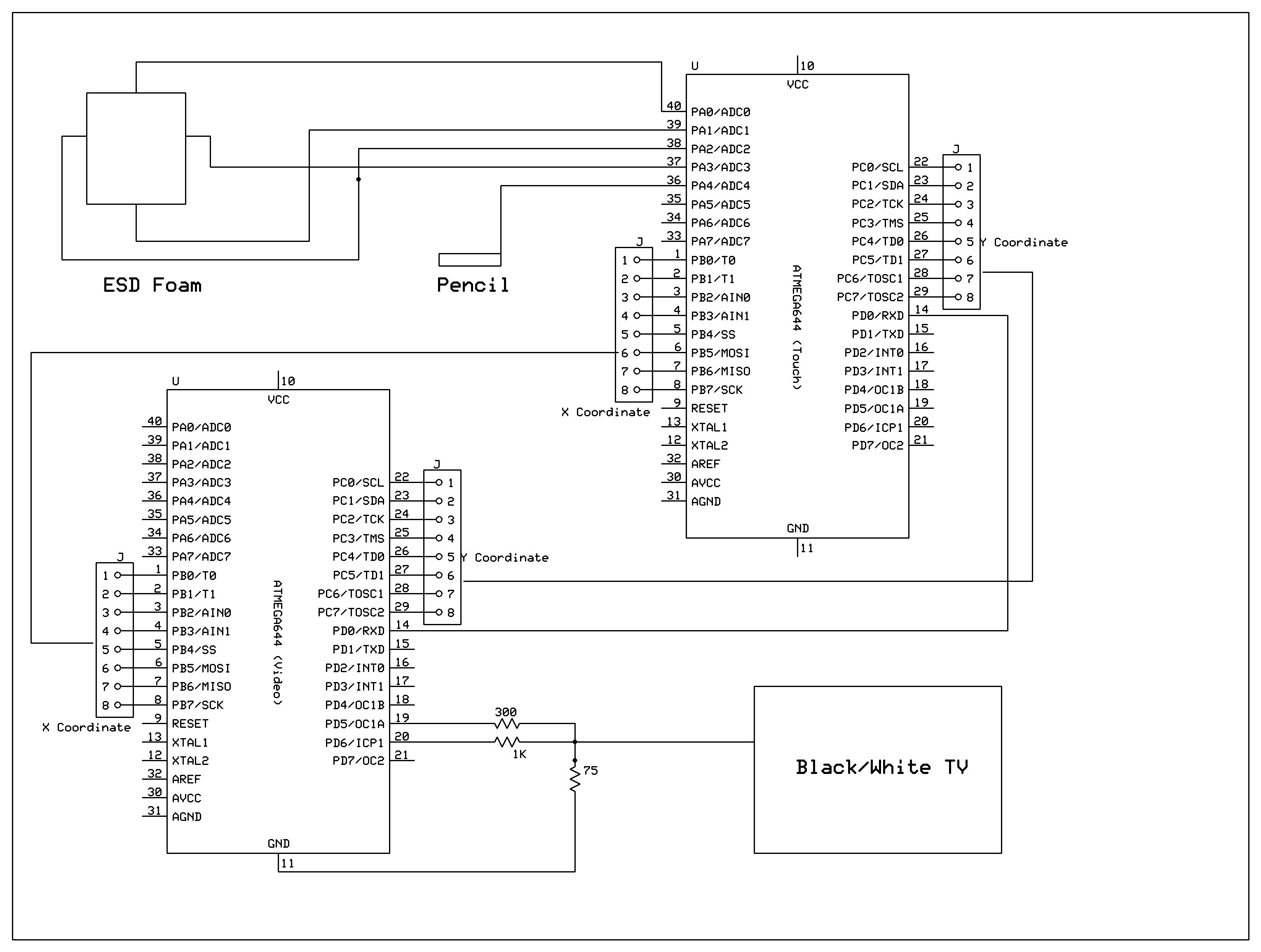
The ESD foam only provided the hardware solution to the project. We were committed to demonstrating the uses of a touch device as an input method for future lab consideration. We decided to develop a video game that utilized the touch interface as an input, Brick Blaster. The video game, however, only required the use of one-dimensional input device, so we opted to make another program to demonstrate the two-dimensional capabilities of the device. We decided on a drawing program that drew points on a black and white television of a detected touch. The video aspect of this project provided several challenges. The most pertinent challenge was performing calculations for the touch input under the strict requirements of video code. The touch interface also using several interrupts to make the software design easy to implement and understand. With video code, there can only be one interrupt for the timing of sending the signals to the television.
This provided an opportunity to interface two microcontrollers by sending and receiving data between the processors. We use one microcontroller for strictly video generation and video game/drawing logic, while the other handles the calculations for the touch interface. These calculations include Analog to Digital (ADC) conversion for reading the position of the detected touch, calibration of the raw ADC values to television pixels, and determining drags and holds on the touch screen.
In order to read the position of a touch, the x and y position must be determined separately by creating a voltage gradient in the orientation that is being read. To create this gradient, we wove bare wire into the foam on each of the four sides, i.e. top, bottom, left, right. We then connect each of the four sides to output ports on the Mega644 MCU and set the sides to either ground or Vcc to create the gradient. When determining the x position of the touch, the top and bottom wires are set at a high impedance state or disconnected from the MCU, while the left side is set to ground and the right side is set to Vcc. This creates a voltage gradient through the ESD foam from left to right, ground to Vcc. For determining the y position, the left and right side become disconnected or set to a high impedance state, while the top is set at ground and the bottom at Vcc to create the gradient from top to bottom, ground to Vcc. The voltage readings are done by our handy pencil that has a wire as its tip that is connected to an ADC port of the MCU. The pencil MUST be used to touch the foam in order to get a reading. This extra requirement is a result of the extreme simplicity of the touch device.
| Configuration | Top | Bottom | Left | Right | Pencil |
| X-Pos | Hi-Z | Hi-Z | Gnd | Vcc | Hi-Z |
| Y-Pos | Gnd | Vcc | Hi-Z | Hi-Z | Hi-Z |
| Standby | Hi-Z | Hi-Z | Gnd | Gnd | Input |
The readings for the x and y positions are done one after the other, and the raw data is then calibrated to video pixels using the following linear equations provided by Atmel.
The determination of holds and drags also uses methods described by Atmel in their handy application note for implementing a touch interface on a microcontroller. If a touch ends within 100ms then it is determined to be a simple tap. If it however takes more than 100ms, then it is either a drag if the coordinates stored within that time are different or a hold if the coordinates are the same, within reason.
Design Detail
SOFTWARE
Description of Brick Blaster Video Game
The video game we implemented is called Brick Blaster, designed after the famous game, Brick Breaker. Brick Breaker is a single-player multi-level game, similar to pong. In the game, the player controls a paddle at the bottom of the screen (moves left and right only) to keep a ball from falling off the screen. The ball bounces off the paddle and against the walls of the game in hopes of breaking the bricks that are distributed around the screen.
The video game code was originally written using the video code from Lab 4 for the Lunar Lander video game. Although the video game displayed correctly for a given level, the TV quality suffered when implementing additional levels. Since a TV is controlled by periodic synchronization pulses, a late sync pulse results with poor TV picture quality.
The game was designed to have four levels with each level having a different brick setup. As mentioned earlier, the TV picture quality suffered when implementing additional levels. As a result, a different version of the video code, which uses USART as a pixel shift register, was used instead. With this alternate code, the sync signal is on pin D.0 and the video on pin D.1. Instead of having the main put the MCU to sleep, it uses a separate timer interrupt. It sets the USART into MSIPM mode (SPI master mode) which turns off start/stop bits. This modified version allows us to stream pixels at uniform rate without assembler through the USART transmit-double-buffer. Hence, the code can run faster because frame calculations do not have to be precisely timed to fit between frames.
Wall and Paddle Collision Detection
The main components of the game consist of detecting collisions between the ball and other elements, such as the paddle, bricks, or the walls. The easiest to implement was the wall since the video code for Lab 4 was used as a basis. However, when the ball hits the bottom wall, the player loses a life and the settings are again initialized so the player can release the ball from the paddle. The ball was 4×3 pixels, which displayed as a square ball on the TV. The paddle was 2×21 pixels. All objects on the screen were drawn starting from the top-left corner to maintain easier comparisons.
Next, paddle collision was implemented. Detection occurs when the ball is located a line above the paddle (bottom of ball + 1 = top of paddle) and within a given range in the x-direction. For the left bound, we check the right column of the ball in comparison to the left column of the paddle. For the right bound, we check the left column of the ball with the right column of the paddle. Using this detection, we can check when the ball hits the paddle. Due to some undetected collisions that could not be resolved, an alternate method for paddle collision was used. It checks if the ball is between the line above the paddle and the bottom wall, and uses video_set function to check if pixels underneath the ball are white.
Brick Design and Brick Collision
The video game was designed to have up to 16 bricks (4 rows and columns) in the game. Some computations were made to space the bricks evenly across the screen in the x- and y-directions. Each brick was designed to be 11×25 pixels. Each brick is separated from the next brick by 9 pixels in the y-direction and/or 7 pixels in the x-direction.
Detecting brick collision and erasing the correct brick was probably the most troublesome in the video game. When brick collision was first implemented, it was still using the variable speed ball. Brick collision required case by case checks, which included corner hits, top/bottom hits, and left/right hits. The details of brick collision will only be discussed for the single speed ball and the top-left corner of the ball for simplicity. To check if the top-left corner of the ball hits the bottom-right of the brick, we first check the velocity directions. The only way the ball will bounce back in the reverse x- and y- directions occurs when the ball is traveling to the left (vx < 0) and up (vy < 0). Next, we check if the top-left corner pixel of the ball is white and if its neighbor to the right and neighbor below are black. This check is used for a single corner. The same idea is used for the other three corners. To check left/right side collisions, we check if the top-left pixel of the ball is white and the pixel underneath it is white. To check top/bottom collisions, we check if the top-left pixel of the ball is white and the pixel to its right is white. The same idea applies to the other three sides. For varying ball speed, there was double the amount of comparisons.
Ball and Paddle Movement
Let us now consider the update animation of the ball and paddle. Ball movement is quite simple as the ball has no acceleration. It is simply updated by adding the old position with the velocity to obtain the new position. Since the video game was written separately from the hardware, the paddle movement was first controlled by switch buttons on the STK500. The buttons controlled when the ball was released from the paddle and paddle movement in the left and right directions. Each paddle movement button incremented or decremented the paddle position by one pixel in the x-direction. The paddle was limited by the boundaries of the game.
For more detail: ESD Foam Touch Controlled Brick Blaster Using Atmega32