Introduction
Our project measures the user’s skin conductance for monitoring his or her mental state.
Summary
Medical experiments have shown that the magnitude of the electrical conductance in a person’s skin is directly correlated to their emotional state. The short term changes in electrical conductances also correlate with a person’s mental response. We implemented an EDA meter designed to measure skin conductance. Our design includes our own sensor, pushbuttons for user input, and an LCD menu that accesses several software features including an event recorder, waveform capture, an stimulus comparison test, and a simple biofeedback game. The software can also transmit data to the PC, where a java program collects and displays the data over a set interval of time.
High Level Design
Rationale and Sources
Skin conductance is known to be correlated with an individual’s emotional state. It is often used in psychology for quantifying a person’s reaction to different stimulus. It is also often implemented in a traditional lie detectors. The current theory is that a person under arousal generates sweat at the skin that changes the skin’s electrical properties. However, this explanation is still debatable, as some scientists claim that the conductance changes too fast to attribute the cause to sweat.
Because a change in mental state can be observed by the change in skin conductance, the arousal level of a person can be quantified. While one of us is interested in visualizing the meditative experiences, the other wanted to recreate the lie detector test seen in one too many movies. We were also intrigued by this project because of the controversial results found in different studies such as the ‘prestimulus’ response, and the characterization of psychotics using skin conductance patterns. There was also the allure of the use of skin conductance in many parapsychological experiments.
Background Math
Hardware
Please read hardware details first.
We needed to calculate three resistor values and the gain of the differential amplifier depending on the range of skin conductance values we want to measure. Human skin conductance values are supposedly only linear when voltages applied are below 0.5V. So we used a voltage divider to bring the bridge Vdd voltage to 0.5V. This ensures that the highest voltage across the user would never exceed 0.5V.
The relationship between skin conductance and output voltage is summed in one equation:
- C1 = cond of resistor in series with finger – placed nearer to Vdd
- C2 = cond of resistor in series with C3 – placed adj to Vdd
- C3 = cond of resistor in series with C2 – placed adj to Gnd
- G = Gain of differential amplifier
- Vo = 0.5V x (C1/(C1+S) – C2/(C2+C3)) x G
At first we met with the problem that the relationship between skin conductance S and output voltage Vo is not linear. The following graph displays resistor values and gain chosen for a skin conductance range of (2uS – 50uS). One can see that the resolution for skin conductance is ridiculously good below 5uS but suffers as the skin conductance climbs.
Eventually, we came to realize that we can linearize the curve by choosing C1 as large as possible. We ended up revising the skin conductance range to (2uS – 25uS) and a C1 value of 500uS (2kOhms). C2, C3, G are all calculated based on the skin conductance range constraint. This gave us a consistent skin conductance resolution over all voltages. The matlab script for generating these solutions can be found in the appendix.
A passive low pass filter was created to filter the output with cutoff frequency of 0.5 Hz.
- R = 3.3 M
- C = 0.1 u
- f = 1/(pi 2 R C) = .48 Hz
Software
To convert 10-bit ADC value to a high resolution voltage. ADCW contains the 10-bit value at the most significant end.
- 5V / 1024b = .004V / b
- Therefore, voltage must be measured in centi-volts.
- Ai = ADCW
- Vo = Ain x 500cV / 1024b x 2
- Vo = Ain x 125cV / 128b
To convert Vo to skin conductance value in uS. Skin conductance value will be stored as hundreds of microsiemens. The reason that the skin conductance values are stored to values beyond their absolute accuracy (.046uS) is because in software we will run a gaussian smoothing filter to interpolate the data.
- (25uS – 2uS) x 100 / 500cV = 4.6 cuS / cV
- S = 2500 cuS – ( 4.6 cus/cV x Vo )
We used a gaussian smoothing filter to smooth the skin conductance values. To increase speed of execution, we implemented the filter in fixed point notation.
- [.006 .061 .242 .383 .242 .061 .006]
- sums -> 1
- [2 16 61 97 61 16 2]
- sums -> 256
Logical Structure
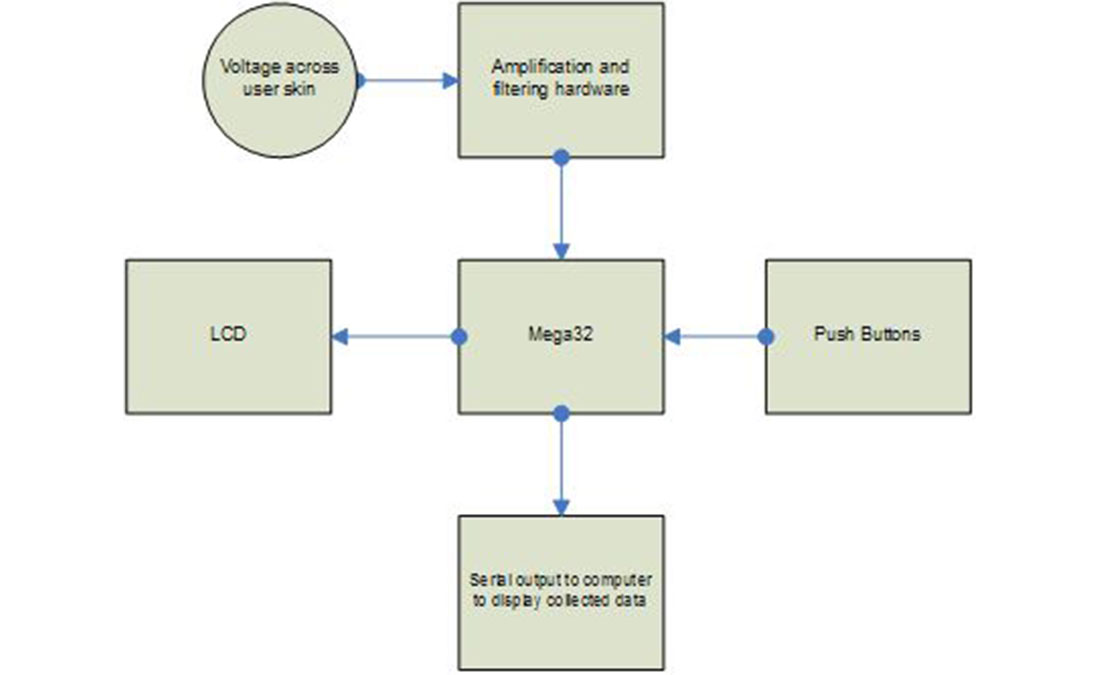
Our GSR design is based around the Mega32 microcontroller. Skin conductance readings are taken from a test subject and are amplified and filtered using our hardware design seen in the hardware section of the lab. We send the signal to the Mega32 through PortA0, the input to the ADC. We programmed the Mega32 for 10-bit ADC to increase the resolution of the data. The pushbuttons allows the user to select and interact with different softwares: detect events, waveform capture, stimulus comparison, and a biofeedback game. The data collected under the different modes are processed and output to the LCD. We also have a serial connection that can be connected to a computer. A java program reads from the serial port using a freeware communications package. It then collects the skin conductance values and outputs to a graph generated by a freeware charting package
Hardware/Software tradeoffs
Because our hardware is not as technically rigorous as some other projects, we spent much time to enhance the software elements. By adding many interesting features to the software, we feel that we compensated for the lack of difficulty in our hardware with the blood and sweat we put into hours of debugging.
Relationship of design to existing standards
Since this device is connected to a human, we had to comply to the class safety standard that there should never be a connection from the human to the 120 V power grid. Furthermore, we made sure that the electrode placement would never be on opposite sides of the body given that even small currents can cause fibrillation in the heart.
Existing patents, copyrights, and trademarks
There should be no patent, copyright or trademark infringement issues in our project as all work is our own and we did not modify preexisting design. Sources of inspiration and help are listed in the references section.
Software/Hardware Design
Hardware details
Skin conductance circuit
A wheatstone bridge is implemented to measure skin conductance. The voltage across the bridge can be used to extrapolate the skin conductance. We feed the voltage at both ends of the bridge to a voltage follower and then into a differential amplifier. The output of the differential amplifier is fed into a low pass filter of cutoff frequency 0.5Hz, and then into PortA0, where ADC takes place.
We built the hardware during one lab period. It would undercome many revisions down the road, but at the time, we were uncertain of whether the hardware was working at all. It was then that we realized that simply acquiring the skin conductance value is not enough; we needed to graph the skin conductance over a range of time. Without visualization, we will never be certain of the data. A week later, we had coded out a java program to collect and display the data. But even then we were still not sure what we were looking at. Two amazing things happened to us. First we decided to scratch the aluminum electrodes we had been working on. Second, we found a video on the internet that is guaranteed to scare whoever watches it. The graph worked wonderfully. The increase in skin conductance caused by the video also gave us new confidence in the data we were collecting. Below are two examples to establish the genuine nature of the data we were collecting. Left shows a graph of 5 minutes of activity. Another 5 minutes devoted to meditation shows a radically cleaner graph, free from waveforms.
Electrodes
We fabricated our own electrodes using o-rings and wire from lab. Although not ideal, we found that our design gave superb readings for our purposes. We have 2 electrodes that are placed at the distal phalanges of the index and middle finger. The electrodes are then connected to the ends of the wheatstone bridge.
LCD
The LCD is connected to the Mega32 through the PortC pins as was done in Lab 1. The pin connections are shown in Lab 1 which can be reached through the reference section. The LCD is the interface between the user and the various skin conductance programs within the MCU.
The pushbuttons are connected to PortA of the Mega32. They allow the user to control the different settings of our design. If pressed, the pushbutton is shorted to a ground connection and an output low signal is seen by the Mega32.
Mega32

We used the Mega32 for analog-digital conversion, reading inputs from pushbuttons, and outputting to the LCD.
Power source
We powered our design using a 9V battery that was regulated down to 5V for the purposed of the Mega32. We did not use power from a wall socket, as any path connecting a human being to the power grid was an unacceptable safety hazard for this lab.
Software details
We had considered cramming as many skin conductance values into SRAM as we possible can, and then display it graphically on the portable black and white TV. However, when a Java serials communication and charting package got into our hands, we realized we could take the alternative approach of simply sending all data to the pc for processing and display. This gave us the opportunity to focus on more rewarding software implementations.
The difficulty in doing the software is the inability to visualize the skin conductance values in real time. If building a robot, and the robot stops moving, it is obvious a bug exists in the program. When measuring skin conductance, we were never really certain if the data we collected was correct unless it was radically off mark. Debugging became a nightmare, as the skin conductance charts became our only window for looking into our mistakes.
Parts List:
| Item | Cost | Note |
|---|---|---|
| Custom PC board: | $5.00 | |
| MAX233CPP RS232 Driver RS232 connector |
$8.00 | |
| Mega32 | $8.00 | |
| LCD | $8.00 | |
| Pushbuttons | $3.00 | |
| Casing | $3.00 | |
| 9V Battery | $2.00 | |
| 16MHz Crystal | $1.00 | |
| Whiteboard | $0.00 | ece210 |
| 3 LMC7111 Op-Amps | $0.00 | from lab |
| RC & Wires | $0.00 | from lab |
| Total | $38.00 |
For more detail: Galvanic skin response meter using Atmel mega32