The Graphical LCD Text Display is complete! I’ve used the same Atmel ATMega8 controller that I used in the Composite Video Display. The interface is the same as well; an 8 bit parallel port with a strobe input and a busy output. It can be connected directly to a 65C22 8 bit port or any generic parallel port with ease.
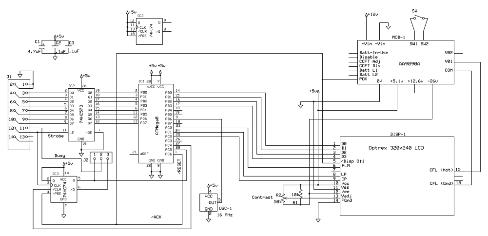
The Display is an Optrex DMF50840A which supports 320×240 with a Cold Compact Flourescent Lamp as the backlight.
The power supply is an ASTEC AA9090A. It has a 6-12vdc input and supplies 5vdc, 12vdc, -26vdc, and 350vac. The -26v and 350v are used by the Display for contrast and the backlight.
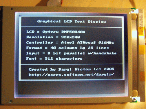
Here is a sample of the display. I use only 320×200 (40×25 characters) as that’s all the character space the ATMega8 can support.
You can enable one of the two sets at any time. The primary font provides all 256 standard DOS characters, The alternate font provides 128 characters and the inverse of each. These are accessed by using toggle commands as defined below:
Lower = the lower 128 characters with the supported control characters (see description below).
Upper = the upper 128 characters including the box drawing characters in Primary mode, inverse characters in Alternate mode.
Primary Font Select = Enable the 256 DOS character set.
Alternate Font Select = Enable a subset of 128 characters with Inverse video support.
See the Command Bytes below for the specific toggle commands.
The firmware is complete and the prototype assembled and tested! The source code for the ATMega8 is now available in the Downloads section. Here is a picture of the completed circuit. The board on the upper left is a modified Composite Text Display board. The top center board is used to tie everything together and has the contrast control.
Here’s how the interface works:
The Host polls the Busy line and waits for it to go inactive (J2 selects active high or active low), then loads the data onto the data bus and clocks the strobe high. The Busy line will go active and stay active until the data has been processed. The time it takes to process a data byte depends upon several factors, including display refresh operations and display movements such as scrolling.
Here is a simple timing diagram:
The 74HC573 Octal Latch is not necessary as long as you leave the data inputs stable until the Busy Flag is reset, but I decided to add it to make the circuit more versatile. The 74HC74 D Flip-flop acts as the strobe latch and Busy Flag, which ensures the host’s strobes are not missed by the ATMega8 during screen refresh. All timing and control is provided by the ATMega8’s program running at 16 MHz. J2 selects the Busy Output logic level, short pins 1-2 for Active High or pins 2-3 for active low.
For more detail: Graphical LCD Text Display


