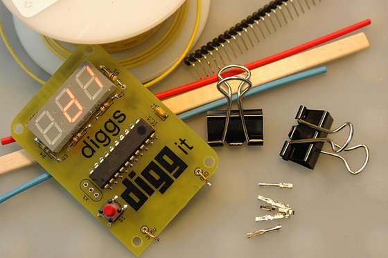
The Digg Button from adafruit industries www.adafruit.com is a very simple DIY electronics kit suitable for beginners. It consists of a microprocessor, a 3-digit display, a button and some available i/o pins.
As it comes from adafruit, it’s a counter that displays the number of times it’s button has been pressed. The open i/o lines can be connected with jumpers (small pieces of wire) to produce a couple of different behaviors.
But, with a simple parallel interface connecting it to a computer, it can be a sturdy platform for experimenting with microprocessor programming.
The site, [www.ladyada.net], which has all the instructions and support forums for adafruit products, has instructions for some simple software hacks based on ponyprog 2000, a program for communicating with the microprocessor. The site also describes how to make a simple parallel port connector to connect the Digg Button to your computer. The description is very straight forward, but it requires soldering the connector to the Digg Button. This is not conducive to hacking your button then displaying your warez.
SO, since I like showing off what I do, I designed a simple clip-on connector that allows me to easily connect and disconnect my Digg Button for hacking. I also created a modded version of the Button firmware, which I’m calling diggX, that can be uploaded using this cable and can itself be hacked using ponyprog 2000.
Here’s a video demo that shows the connector in use and describes the firmware hack:
Time Required:
Should be easy to finish this in an hour
Supplies:
-
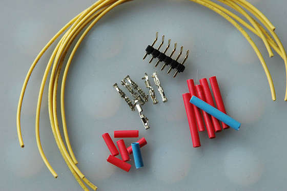
- (1) Right-angle break-away pin header strip with at least 6 pins spaced at .1″ (Jameco #686111 — this is a 6-position header, you might order several, or get a longer one in case you mess one up)
- (1) Several feet of #24 stranded hook-up wire (Jameco #734405. Yellow. This is for a 100′ roll which is a little overkill. RadioShack has #22 hook-up wire which would technically work, but will be a little bulkier.)
- (6) Connector socket pins (optional. Jameco #496421, these are the cheap ones. You can get pricier versions with different metal, but these seem to work OK)
- (1) 8″ or so of 1/16″ heat shrink tubing (only 3″ needed if not using the socket pins. Jameco #419127, black)
- (1) D-Sub Connector with solder terminals (male or female, see text. Jameco #223010 for male, #223079 for female.)
- (3) ~1k ohm resistors (Jameco #690865, this is for quantity 100. You can get in sets of 5 from RadioShack)
- (1) Fast setting epoxy (5-minute, or so, available everywhere). Epoxy putty also works fine.
- (1) Short piece of “hobby stick”, a couple of inches long
- (2) Small binder clips (from any office supply, the 3/4″ ones are a good size)
The connector socket pins are used at one end of the cable wires so the cable can be easily hooked up to a parallel port or other interface if needed–and, removed later. If you want, you can solder the wires directly–in this case to the D-Sub connector–obviating the need for these. One advantage of using the socket pins is that if you later want to connect the cable to a serial programmer (works with my AVRDragon just fine), you can just move the wires to the serial connector without resoldering. But, it’s up to you.
If you are going to connect the cable directly to your computer port, you’ll probably need a male connector. On the other hand, that isn’t very convenient. You’re always having to look around behind your computer to see what’s going on with the Button. For a few dollars, you can buy a “straight-through” parallel cable that plugs into your computer port on one side and the interface cable you’re building on the other. That’s what I use. It has male connectors on both ends. In that case, you should get a “female” D-Sub connector so it’ll plug into the cable.
Make sure to use stranded wire, solid wire would be too stiff and difficult to handle (though it *would* technically work)
Tools (some of which you’ll probably have if you built the Digg Button to begin with):
-
- Wire cutters
- Small pliers (I actually use small jewelry pliers I got from a craft store)
- Soldering Iron and Solder (standard 60/40 thin-ish electronics solder)
- Hair dryer (hot) or heat gun for shrinking tubing
Optional, but infinitely worth their weight:
-
- Wire strippers (I use the very simple type shown in the photos and they work fine)
- Small project vise (e.g. PanaVise Jr.)
I’m assuming you know how to solder. If not, you can check out the NASA videos on their radiojove site, http://radiojove.gsfc.nasa.gov/telescope/soldering.htm, which is a very cool radio telescope project of its own.
Now, assuming you’ve gathered everything together, on to the building part.
Step 1 Prepare the 6-Pin Connector
If you look at the back of the Digg Button circuit board, you’ll see six small connector pads at the top. This is where the connector attaches. It turns out that the pad centers are spaced .1″ apart which is one of the standard board spacings. That’s lucky for us, because the pin headers have pins also spaced at .1″.
To make talking about the connector pads on the circuit board easier I’m going to assign the letters A-F to the pads. If the back of the board is towards you facing right, the pad on the top is “A”, the next one is “B”, etc. until the pad on the bottom, which would be “F”. Note: I’m talking about the little pads which are actually connected to the circuit, not the big wide pads that go nowhere.
Anyway, you may have a right-angle pin header that has more than six pins. Technically, you only need five pins to connect to the D-Sub connector, but I think it’s easier to avoid mistakes in clipping the header to your Digg Button to use all six pads. In this case, you need to break off (or, clip off) a six-pin section to use for your connector.
The header pins will be clipped to the board with the right-angle part touching the board and the other end of the pins facing back away from the board. Notice which is the “A” pin, “B” pin, etc.
Step 2 Prepare the Wires
Now, you need to prepare the wires for the cable. If you’re soldering directly to the D-Sub connector you probably only need to use five wires (Pin “A” is the one not used), but I’m assuming that you’ll be making a general cable and will use all six. Building a “universal” cable with six wires and connectors on one end will allow you to connect the cable to an ISP programmer if you want to later (I’ve successfully connected my Digg Button to the AVRDragon). But, that’s out-of-scope right now.
I made my wires 6″ long. I was thinking I didn’t want them too long to avoid any kind of electrical interference that sometimes comes from long bits of wire. But, in retrospect I think 8″ or 10″ probably would have been OK and would have been more convenient. So, cut six (or five) bits of wire to the length you want.
After the wires are cut, strip about 1/8″ off each end (this is where the wire stripper will save you much grief!).
To make the wires easier to solder later, “tin” the ends of the wire by melting a very small amount of solder on each end. Be careful not to heat the wires too much, or the insulation will melt making them a little harder to work with later.
Step 3 Prepare the Heat-Shrink Tubing
Heat-shrink tubing is used to isolate the wires at the connector ends. If you are also using the socket pins, the tubing will fit over the pins to stabilize them and make them easier to handle.
Actually, when I first designed this, I hadn’t planned on using epoxy on the connector, so needed something to make sure wires didn’t touch each other on that end. If you use epoxy (or epoxy putty) you don’t actually need the bits of heat-shrink tubing there, though they do add a nice bit of color if you use clear epoxy. SO, use them or not.
For the six (or five) bits near the right-angle pin header, you can use 1/4″ pieces of tubing. For the other end, 3/4″ is necessary. If you don’t want to think too much, you can probably just cut all tubing pieces to 3/4″. Note, that I used two different colors making the “F” pin different from the others just to make it easy to recognize for orientation.
Step 4 (Optional) Solder the Socket Connectors to One End of the Wires
If you’re going to solder your wires directly to the D-Sub connector, you can skip this step. But, you might want to read through it anyway. It’s a handy technique I use often to make removable wires.
This is a fiddly procedure, but basically you place the wire in the connector and crimp it with some small pliers to hold it in place while you solder it. Then you finish the crimping job to make it more solid.
Look at the pictures. They’re probably more clear than anything I could write.
Until you solder the wire in the connector, the assembly is pretty fragile. I use an alligator clip epoxied to a small wood square to help hold things when I need a third hand. There are other ways to do it (like using a friend). But, it’s best to hold the *connector* rather than the wire. Otherwise, it’s not stable enough to solder.
When you solder, you should make it pretty swift, or you can melt the insulation and then sometimes the wire will fall out. But, you’ll get the hang of it.
After the solder has cooled, complete the crimp with pliers to hold the wire in place.
Step 5 Solder the Wires to the Pin Connector
Now, its time to solder the wires to the pin connector. Its the touchiest part. If you use too much heat you can melt the plastic around the pins and they’ll begin to wobble. So, I think it’s best to use your vise (or something else) to hold the header while you make quick solder connections. The other important technique is to “tin” the pin header just like you did the wire (but, with a little more solder). Then you can just heat up the wire and pin to melt their solder together and you have a joint.
Once the header pins have cooled from tinning, solder the first wire on. Start at one end of the header and work towards the other to make it easier to get the soldering tip close to the solder connection. Note that you’re soldering to the shorter, non-right-angle part of each pin. The only thing holding each wire to its pin, is the solder. Try to make the wires extend directly away from each pin rather than at any angle.
When all the wires are soldered and cooled, it can help stabilize the header if you slide the plastic strip as far away from the solder connection as possible. The easiest way to do this is to put the header/wire assembly on the table with the wires facing straight up. Use a small screw driver to carefully press the plastic between the pins towards the table. With the right amount of pressure the plastic will begin to slide.
For more Detail: Hacking your Digg Button with a Removable Interface Cable using AVR


