A alimentação é feita por 2 pilhas AAA de 1.2V ( recarregáveis ).
A escolha para se usar apenas 2 pilhas AAA é principalmente reduzir ao máximo o peso a transportar pelo helicoptero.
Uma vez que 2 pilhas recarregaveis AAA só fornecem 2.4V e é necessário pelo menos 5V para atingir os níveis TTL na saida RS232 foi usado um conversor DC-DC em tamanho SMD fornecendo a todo o circuito 5V.
The power source is from 2 AAA batteries 1.2V (rechargeable).
The choice to use the two AAA batteries is mainly to reduce the weight to be transported by helicopter.
Since both rechargeable AAA batteries only provide 2.4V and because 5V is needed at least to achieve TTL levels used in RS232 output i included a small DC-DC converter providing 5V to the entire circuit.
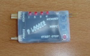
Tem 4 leds vermelhos que correspondem a cada memoria e um led bi-color que indica o estado do registador ( verde= leitura, vermelho= gravação e apagado=reset ás memórias ).
Como interface tem 3 botões ( mudar o estado, aceder ás memorias e start/stop ).
O primeiro botão selecciona a memoria.
O segundo botão muda o estado ( leitura, gravação ou apagar memória ).
O terceiro botão apenas inicia ou pára o processo de leitura ou gravação dependendo do modo que está.
It has 3 connectors (connection to the temperature sensor, power input and RS232 output data).
It has 4 red LEDs that correspond to each memory and a dual-color LED to display the Logger status (green = read, write and red = off = reset memories).
For controlling the logger i placed 3 buttons (change the state, access memories and start/stop).
The first button selects the memory.
The second button changes the state (read, write or erase memory).
The third button only starts or stops the process of reading or writing depending on the way it is.
Para um acabamento melhor, desenhei uma pequena folha com a indicação das fichas, leds e botões e também com o nome do circuito.
No exterior, e como existe sempre salpicos de combustivel, coloquei manga termo-retractil transparente.
For a better look, I designed a small paper sheet indicating the chips, LEDs and buttons and also with the circuit name.
For the external cover, and because there is always fuel splashes, i covered the circuit with a transparent heat shrink tube.
Para extração dos dados liga-se por RS232 a um computador e os dados são descarregados da memória que está seleccionada.
For data extraction i connect the circuit to the PC using a RS232 cable and data are downloaded from then memory block selected.
Para melhor visualizar e trabalhar os dados fiz uma folha em excel com uma macro que importa e gera gráficos com os dados obtidos.
To better visualize the data i made an excel sheet with a macro that imports and generates graphics with the data obtained.

