Introduction
My final project creates a relatively high resolution color TV display by using two microcontrollers with shared access to external memory.
In the fall of 2005, I worked on a microcontroller project to create color video using an Atmel microcontroller. I had soon realized that since the microcontrollers have a very small amount of SRAM in them (even the mega128 only has 4kB), the resolution that could be achieved without external SRAM would not be very high. In fact, I was only able to achieve about 64×100 pixels for a color TV display, with 4 bit color, using a mega32. I was unhappy with these results however, so I wanted to try and increase the resolution that I could achieve by utilizing external memory to hold the video data.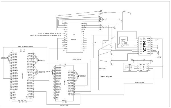
My experience with the previous project also made me realize that even if I did use external memory to display to a color television, I would never have the time in between frames to perform the necessary calculations and update the external memory. I decided to add a second microcontroller that would access and change the memory between frames and could also perform calculation while the first microcontroller was pushing the external memory contents to a set of DACs.
High-Level Design
As previously mentioned, I had decided to work on this project because I wanted to improve a project I had worked on in the fall of 2005. This project can be seen at Color Video Generation with the mega32 microcontroller.
The basic idea of the project is that one microcontroller handles all the calculations and memory updates, while the other handles the NTSC encoding. A block diagram can be seen below:
Hardware and Software Tradeoffs
When I originally began the project, I planned on using two 8 bit counters which the mega32 would increment in order to access the SRAM. I also planned on using a latch to free up an I/O port on the mega128. I soon realized that using these parts added a layer of complexity, so I decided to remove them, in order to simplify the design. In addition, these parts also slowed down the rate at which the memory could be accessed, decreasing the number of pixels that could be displayed on a line and decreasing the number of pixels that could be accessed during the frame downtime.
When I used a single microcontroller to display the color data, I could change the level of the color bits at will. This was helpful, because at the end of a line, the RGB inputs have to be grounded, so they do not mess up the sync signal. Unfortunately, when I added the SRAM, I did not have such control, because the data was totally controlled by what was in the SRAM, and putting the SRAM in a high-Z state made the inputs floating instead of grounded. There were a few solutions to this problem: The first would involve placing black pixels at the end of each line, so that when the inputs were placed in a high-Z state, they would already have been grounded. The second solution was to ground the inputs, using transistors. I decided that this was the best option, because it would allow the user to access the full range of memory and was not too complex to put together.
Standards
In order to create color video, I had to conform to the NTSC color TV standard. This was not too difficult, as all of the sync and color subcarrier information was taken care of by the ELM304 and the AD724.
Hardware Design
Based on the supplied schematic in the appendix, it should be fairly easy for someone to create the same design. I would advise against using binary counter ICs as previously mentioned, unless they are extremely fast, because the added delay may have an effect the quality on the screen. In addition, it would be a good idea to try and keep the wires as short as possible to limit the effects of EMI.
The hardware design I used for the mega32/ELM304 interface is similar to what I used in my previous project, but I added a connection to pin6 on the elm304, because this pin went high when in the display portion of the signal. I borrowed this idea from another group attempting a similar project to my own (ECE 476 Final Project: High-Resolution Color Television by Keith Jamison and Morgan Winer) because it allowed an easy way of knowing when to access the SRAM without having to keep track of line numbers. I also changed the DAC set up, removing one bit from green and adding it to blue in order to allow blue for a few more shades of blue. I had sampled two DACs from Analog Devices, but I did not have time to solder them on to prototype boards and then figure out how to use them, so I just went with a simple resistor network. Before entering the RGB inputs of the AD724, each input was connected to the collector pin of an NPN transistor and the emitter was connected to ground. The bases of these transistors were connected to PORTD.4 on the mega32, so whenever the port pin went high, the RGB inputs would be forced to ground, effectively shutting off the DACs. This was also useful for when the mega128 was accessing the memory because the data pins are both input and output and the mega128 could destroy the sync signal while it was changing the contents of the memory. If I was able to sample and use dual port SRAM this could be avoided, but the 3 NPN transistors worked out perfectly well.
Two pins on the mega32 and mega128 were used to communicate between each other. One pin told the mega32 when the mega128 was finished accessing the SRAM. This was used during the initialization sequence, since erasing the entire contents of the memory array would take about 80ms. In addition, if I wanted to set the background to a certain color or set of colors, this could also be done at this time. The other pin would inform the mega128 when the mega32 was finished displaying the contents of the memory. There are two options that could be taken at this point. If the mega128 has a great deal to write to the screen, it could inform the mega32 of this by pulling the first communication pin low. This will turn off the display until the pin changes its state, but the screen will also blank if this is done, so care should be taken when doing this. It may be possible to skip a few frames for a loading sequence, but every other frame should not be skipped. An interlaced display running at 30Hz looks horrible, and will cause most people to feel some slight discomfort, so care should be taken that all display code will finish in one frame. Another option, if the mega128 does not have very much to write to the screen, could be to write whatever is necessary without changing the first communication pin. One thing to keep in mind is that when changing who has control of the memory, the port pins accessing the address bus and/or the data bus on the disabled microcontroller are in a high-Z state. If this did not occur, a large amount of current could be drawn and/or the voltage levels could drop to unacceptable TTL levels.
Parts List:
| STK501 (rental) |
$15 |
| mega128 (rental) |
$8 |
| White Board (rental) |
$6 |
| PC board |
$5 |
| Color TV (rental) |
$10 |
| Memory |
$3.98 |
| Stuff I didn’t use, but purchased | |
|
$0.55 |
|
$0.66 |
| Stuff from my previous project |
Free |
|
– |
|
– |
|
– |
|
– |
|
– |
|
– |
| Total |
49.85 |
For more detail: High-Resolution Color TV Using Two Microcontrollers