The goal of this project was to build a versatile, yet easy to use, sensor-triggered camera controller for high speed photography.
Dan Furie (djf35)
Scott Linderman (swl28)

High Level Design
Inspiration
Our motivation came from photographs that captured a very small moment in time, such as a water droplet splattering from a faucet or a balloon during the split second that it was bursting. Human reaction, and even a camera’s shutter mechanisms, are too slow to reliably capture such precise moments in time. To overcome these limitations, we decided to employ a microcontroller hooked into various sensors and a high intensity LED array to control the shutter of the camera. Photographers interested in taking such pictures normally have to spend a lot of money on specialized equipment and lighting controllers, or they have to take hundreds of pictures and hope to get lucky. Our goal was to cheaply create a reliable system for high speed photography.
Concept
We decided to build our system using an interface similar to that of a cellular phone. An inexpensive color LCD, approximately 1″x1″, coupled with a keypad taken from a Motorola RAZR provided a very convenient way to control the camera. A hierarchical menu system allows the user to set thresholds for sensors as well as other parameters of the shot, and then to initiate the shot by waiting for the triggers to fire. Various sensors were built to allow the user to take shots triggered acoustically, via an IR sensor, or even based on impact using an accelerometer. Finally, our homemade flash unit creates a quick and controllable light source to illuminate moving objects at just the right time.
Implementation Details
Hardware
The hardware for this system is comprised of the following
- Sensors
- Microphone
- Accelerometer
- Infrared ranging unit
- Camera shutter control circuit
- High powered LED flash unit
- 132×132 12-bit color LCD
- Keypad
Microphone
The microphone circuit consists of an electrolet microphone and an op-amp set up to be a non-inverting amplifier. The microphone is powered from the MCU board using the +5V rail. The microphone is fed through a 10uF electrolytic capacitor which serves as a decoupling capacitor. The signal is then put into the non-inverting input of the op-amp. The op-amp output is fed back through a potentiometer which serves as a variable gain for the circuit. The potentiometer output is fed back into the inverting input of the op-amp which provides the gain. The LM358 does not provide rail to rail voltages and is only able to provide a maximum of 3.7V output. However, we care very little about total output because we simply need to detect sounds such as snaps or claps. A user defined threshold for taking the picture is provided through the menu system on the LCD. Additionally, a meter on the LCD shows the peak value of the ADC input over 1 second intervals, allowing correction for ambient noise.
IR Sensor
The IR sensor is a very simple device that works by reflecting infrared light off of an object and detecting the reflecting with a photo-transistor that is tuned to the same frequency of light. The LED is mounted next to the photo-transistor, however, the emitted light from the LED does not directly shine into the photo-transistor. Appropriate values for resistance are in series with both the LED to limit current and the photo-transistor in order to show a voltage drop based on distance to the object in front of the sensor. The effective range of the sensor is a few centimeters. Object detection can be enhanced by placing a reflective surface between the object and the sensor. When the object passes between the sensor and reflective surface, a large drop will be observed in the output signal.
Accelerometer
The accelerometer is very simple to use. The one being used is designed for automotive applications and is packaged in an extremely sturdy casing. This serves us well because we are using it to sense impacts of various types. The interface for the sensor is also very easy to use; the output signal is a voltage linearly related to the detected acceleration. Like the other sensors, an on-screen meter allows the user to set the threshold based on the detected peak values over 1 second intervals.
Flash Unit
The flash unit consists of 5 3Watt LEDs in series with a BUZ73 power nmos transistor and a 1N4001 diode. The entire series is powered with a 20V power charger for an old laptop. This charger is an ideal power source because it provides a high current output along with a high voltage, all in a relatively compact form factor. Each LED drops about 3.7V, and the diode drops between .7 and 1V depending on the voltage. This helps to regulate the amount of current going through the LEDs. The LEDs are mounted on a piece of scrap aluminum with thermally conductive adhesive which prevents the LEDs from overheating.
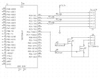
LCD & Shutter Control
The shutter is controlled by a single npn mosfet. The camera is designed for remote shutter operation using a 2.5mm stereo mini-jack. When the middle pin is shorted with the first pin, the shutter is opened. The npn mosfet serves as a simple switch that shorts than pin when the gate is driven high by the MCU. The LCD is powered by an external 2xAA battery pack which provides the 3.3V needed by the sparkfun carrier board. Because the MCU drives its pin to 5V and the LCD takes a 3.3V signal input, a 1k resistor was placed in between the MCU and the LCD which drops the signal to an appropriate voltage for the LCD
Parts List:
| Part | Cost |
|---|---|
|
—
|
$46.75
|
| Custom PC Board | $5 |
| 2x Small Solder Board | $4 |
| Large Solder Board | $2.50 |
| Power Supply | $5 |
| ATMEGA32 | $8 |
| 20x Header Pin | $1 |
| 2x DIP Socket | $1 |
| 5x Luxeon 3Watt LED | $20.25 |
| Electrolet Microphone | Previously had |
| 2.5mm Stereo cable & jack | Previously had |
| LM358 | From lab |
| IR LED | From lab |
| IR Photo-transistor | From lab |
| BUZ73 | From lab |
| 1n4001 Diode | From lab |
| Resistors & Capacitors | From lab |
| Sensata Automotive 10g single-axis accelerometer | Surplus from FSAE car lab |
| LCD & carrier board | Previously had |
| 19.5V Power Supply | Leftover from an old broken laptop |
| Scrap aluminum | Scrap from the FSAE lab |
| Push buttons | Previously had |
For more detail: High Speed Photography Controller Using Atmega32