Introduction
For our final project we decided to build a robot that could navigate from one location to any given target and avoid obstacles in its way. The robot body used a very primitive design that included a cardboard box for the body and Minute Maid wheel caps. A two wheeled design for the robot allowed us to program the bot so that it could turn while remaining in its position. Stepper motors were used to propel the wheels and navigation and obstacle avoidance was implemented using IR sensors.

High Level Design
The inspiration for the robot and its functionality, as mentioned briefly in the summary, came from our second-last project in ECE 314. We had to design a mechanism using the philosophy of state machines to make a robot move from its home to a target to steal a flag and then come back, all the while avoiding collision with tricky obstacles and also simultaneously avoiding and beating the competitors robot which was trying to do the same.
Obstacle avoidance seemed fairly straight forward and there were a number of sensors on the market that would do the job. We chose the Sharp IR Distance ranging sensor due to its low cost. Accuracy in distance was not an issue for us since we just needed to know if or not there was an obstacle in our way. We thus decided against using the Devantech sensor which was fairly expensive and would eat into our budget completely.
Target finding was a more difficult thing to implement from both the hardware and software perspective. We experimented with various IR led transmitters and photo transistors but were unable to acquire any decent signal beyond 2 feet. We also experimented with the idea of using dead reckoning.
Target finding was a more difficult thing to implement from both the hardware and software perspective. We experimented with various IR led transmitters and photo transistors but were unable to acquire any decent signal beyond 2 feet. We also experimented with the idea of using dead reckoning.
Given that we were using stepper motors for movement, it was theoretically possible to measure the distance moved by each wheel. Also knowing that our bot turned in the same place we could track the angle that the bot rotated by and use that for any subsequent distance measurements with respect to our target location. This however failed since the stepper motors skipped a considerable amount as they were not powerful enough to deliver a steady torque to the wheels.
Two weeks into the project we stumbled across the idea of using a standard TV remote control for target finding. From experience we knew that the IR remote control had a fairly good range of about 10 feet or so. What we needed were some sensors that could pick up this signal. We were able to sample 4 IR 38 Khz Vishay sensors from Newark One Electronics. The combination of the IR remote and sensor helped us address the problem of target finding.
The bot body was constructed out of a simple cardboard box. Minute maid caps were used as rear wheels and a ping pong ball was used as a third supporting wheel.
Hardware Design
Motion:
Bot movement was achieved using 2 stepper motors that were provided by Prof. Land. We made extensive use of the Vertical Plotter project, SP 01 for understanding the operation of the stepper motors.
The operation of these 7.5 degree stepper motors is documented below. The motors had 2 brown leads that needed to be connected to Vcc. The rest of the wires had to be excited in the sequence of brown, red, orange and white to operate the motor. The following sequence was used to test the motor operation in the beginning.
Thereafter to provide more torque to the motor 2 of the wires were excited at a time in the following sequence to provide a half step at every cycle. When operated at 12 V the motors provided us with sufficient torque to move the bot.
As a first step the motors were driven using the TIP31C transistors. To drive each of the 2 motors we would need 8 of these transistors and assembling the circuit would be cumbersome. Also the circuit with 8 transistors would occupy a considerable amount of space on the bot whose size was limited. We thus decided to use the ULN2003 chip to drive the motor and isolate them from the microcontroller. The microcontroller output was connected to pins 1 through 7 on the chip and the output across pins 10 – 12 were connected to the stepper motors. 2 of these chips were used, one for each motor.
The following code was written to step through each of the motors.
A speed differential on the wheels was used to turn the bot. A ping pong ball placed on the front acted as a third supporting wheel. The 2 wheel configuration allowed us to turn the bot in its place.
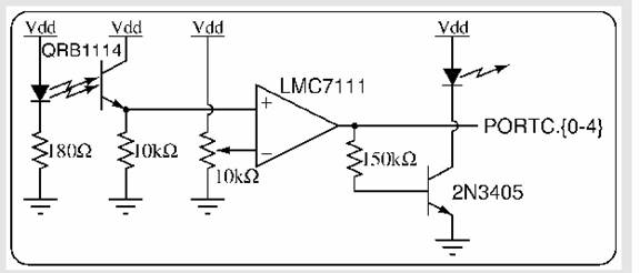
Obstacle Detection:
The Sharp GP2D02 sensor was used for the purpose of obstacle detection. Using the sensor was fairly straightforward. Using the microcontroller, we implemented a state machine which outputted a sequence of signals to the sensor as illustrated below. Once this was done the output of the sensor was read in serially to obtain distance information. If an obstacle was found to be in a vicinity of about 7 cm or closer a flag was set so that the bot would avoid the obstacle.
For more detail: IntelliBOT