Introduction
This project is a proof-of-concept device that transmits an audio signal using a laser beam, while removing the need for the user to align the beam themselves.

For our project, we created a mono-axial transmitter/receiver setup that converts an analog audio signal, via a standard 3.5mm jack, and transmits it via a laser to a receiver, which converts the signal back into audio. The receiver can be rotated within its horizontal plane, and uses a servo motor controlled by a microcontroller to automatically align it with the receiver. The end result is a wireless audio signal that cannot be overheard by other devices.
Project Details
Rationale
Light is already becoming a popular means of communication, thanks to fiber optics, which can guide optical data much like a wire transmits current. It might seem impractical, then, to use lasers without a guiding medium to transmit information. However, in contexts where a physical connection is impossible or unfeasible, and the need for a focused beam arises, it would seem logical to use laser light. In particular, free space laser communication has useful applications to military logistics, where information on the front must be kept limited to friendly ears, and ground-to-air links are important. We decided to create a simple and inexpensive proof-of-concept to demonstrate the advantages of this seemingly impractical scheme.
Inspiration for this project came from a design in the book Gonzo Gizmos: Projects & Devices to Channel Your Inner Geek, a book written by Simon Quellen Field, in which a laser/solar cell combination allowed for the transmission of an audio signal using light. A topic of research at MIT Lincoln Laboratory (http://www.ll.mit.edu/news/freespace-lasercom.html) inspired us to incorporate tracking capability while keeping the project budget affordable at a hobbyist level.
Logical Structure
Our project is divided into two distinct sections: audio transmission via hardware, and alignment control via software. The former can be accomplished once the latter has succeeded, making the two tasks mutually dependent for overall functionality. The alignment is accomplished using a servo motor to rotate the transmitter until it aligns with the receiver. This is done by detecting the light emitted from the receivers laser using a phototransistor. The transmitter scans over its free range until it finds the receiver, at which point the transmitting laser is turned on and the audio signal is picked up by an array of photodiodes. The details of this process are explored below.
Safety and Standards
Since we are using lasers, the effects of exposure need to be considered. The lasers we used were purchased commercially, and comply with class IIIA power and safety specifications, as designated by the ANSI Z136.1 consensus. In the US, ANSI and OHSA standards specify the parameters under which lasers can be safely operated. For a class IIIA laser, the beams are generally not hazardous without the use of focusing equipment, though direct exposure to the eye should be avoided. With this in mind, we operated the device in a plane that lacked reflective objects and was well below eye level. Additionally, the transmitting laser is turned off when the exact direction of the laser is not known (i.e. when the transmitter is scanning the area). The receivers laser is limited to be just bright enough to be detected by the transmitter, but not at the peak amplitude.
Hardware/Software Tradeoffs
The audio signal sent by the transmitter is provided externally rather than via the microcontroller, since external devices represent more flexibility and mobility in the information that can be sent. Having the audio synthesized by the Mega644 would require some form of external memory and a method of flashing from an external source anyways, so we decided to cut out the middleman.
The audio signal is sent via an analog transmission instead of decoding it into a digital signal. Optical transmission is usually done using with digital signals, requiring hardware for decoding at the receiver end. By transmitting the analog audio signal through laser amplitude modulation, we cut down on the transmitter and receiver hardware by eliminating the need for encoding and decoding processors.
Design Details
Hardware
Transmitter
The transmitter is broken down into three circuits. The first circuit, which is similar to the receiver end, is the laser audio transmission circuit. This transmitter works by modulating the amplitude of the laser based on the amplitude of the audio signal that we are trying to transmit.
The audio, which is fed to the circuit through a standard 3.5mm audio jack, is sent to an adder circuit. The adder, shown below, consists of two inputs and a negative feedback resistor that will be summed together. The two connections to the non-inverting input of the op-amp are the audio signal and a DC bias signal that is generally kept at around 3V. This voltage can be modified by adjusting a potentiometer.
The signal to the inverting input of the op-amp is half that of the output, which is obtained by using a voltage divider of two equal resistors. This feedback allows the op-amp to follow the amplitude of the non-inverting input as it attempts to equate the voltages at the two inputs.
The output of the op-amp is sent directly to the laser. The amplitude of the laser is proportional to the voltage that is applied to it. The amplitude linearly follows the voltage up to roughly 4V, at which point the response is more exponential. We are taking advantage of the linear region of the response to send a mostly unmodified audio signal to the receiver for playback.
The laser needs to be turned off while the transmitter is scanning for the receiver, mainly for safety and power reasons. To achieve this, the 9V supply to the op-amp is controlled by an NPN transistor, which can act as a switch controlled by the microcontroller.
The second circuit in the transmitter is based on a phototransistor that responds to red light. When VCE of the transistor is set to 5 volts, the current flowing through the transistor is proportional to the amount of red light that is incident upon the detector. The current flows through the 10K resistor, resulting in a measurable voltage that is proportional to the incident light. This voltage is fed to the analog-to-digital converter of the microcontroller, and determines whether the receiver and transmitter are properly aligned and ready for transmission.
The last piece of the transmitter is the motor controlling circuit. We are using a servo motor to control the direction of the transmission. The motor is opto-isolated from the rest of circuit, and particularly, the microcontroller. This means that the motor is powered by a different power supply, and has no direct connections with any terminal of the microcontroller.
The servo motor is controlled by a pulse, whose length corresponds with the desired position of the motor. Servos can achieve absolute positioning, while other types of motors can only be positioned relative to the current state. The precisely timed pulse is sent through a 330W resistor to the input of the isolator. The output of the isolator is simply the same pulse with a 5 volt amplitude, which is then sent to the motor for positioning.
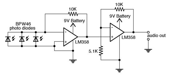
The receiver circuit somewhat resembles the transmitter circuit. Rather than a single phototransistor, however, it instead uses three photodiodes, which have much larger sensitive areas compared to the transistor. Since the response of the diodes directly affects the audio quality, a more complex circuit is called for. The diodes themselves are placed between the two terminals of an op-amp, whose output voltage is determined by the current that flows through the diodes. Using an op-amp instead of biasing the diodes allows us to utilize a near-ideal short-circuit current. With three diodes in parallel, we effectively triple the area upon which we can receive a signal. After amplifying the signal with a second op-amp, the result is then fed directly to an audio jack, where the signal can be heard using any compatible device.
Parts List:
|
Source |
Part No. |
Description |
Unit Price |
Quantity |
| ECE 4760 Lab | — | STK 500 | $15.00 | 1 |
| ECE 4760 Lab | — | 9V Battery | $2.00 | 2 |
| ECE 4760 Lab | — | Solder Board | $1.00 | 2 |
| ECE 4760 Lab | — | DIP Socket | $0.50 | 3 |
| ECE 4760 Lab | — | 1-pin Jumper Cable | $0.50 | 5 |
| ECE 4760 Lab | — | 3.5mm Stereo Jack | — | 2 |
| Adam Shapiro | — | Adjustable clamp | — | 1 |
| dealextreme.com | 22334 | Red Laser Pointer | $1.91 | 2 |
| jameco.com | hs-244 | Servo Motor | $19.95 | 1 |
| digikey.com | BPW46 | Photodiode | $1.01 | 3 |
| digikey.com | LM358ANFS-ND | Op-amp | $0.39 | 2 |
| digikey.com | 160-1304-5-ND | Opto-isolator | $0.32 | 1 |
| digikey.com | 2N3904FS-ND | NPN Transistor | $0.11 | 1 |
| digikey.com | 3386F-103-ND | 10k Potentiometer | $1.14 | 2 |
| digikey.com | AE9919-ND | 3.5mm Audio Cable | $5.10 | 1 |
| allelectronics.com | LT9593-91-0125 | IR Phototransistor | $0.65 | 1 |
|
Total |
$61.04 |
|||
For more detail : Laser Audio Transmitter Using Atmega32