One of the interesting projects for most of the embedded beginners enthusiasts or hobbyists is to build the LED chasing effect. In this project we are going to use both the Arduino IDE and Atmel AVR Studio to program the AVR ATMega168 microcontroller, therefore you could learn to use these well known Integrated Development Environment (IDE) to program the project.
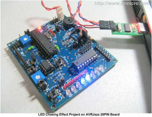
The LED Chasing Project
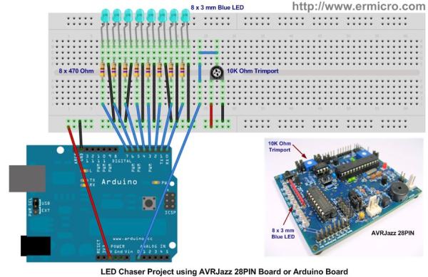
To complete the project you need the AVRJazz 28PIN board from ermicro store or Arduino board with eight 470 Ohm resistors, eight 3 mm LED, one 10K Ohm trimmer potentiometer (trimpot), and breadboard as shown on this following picture:
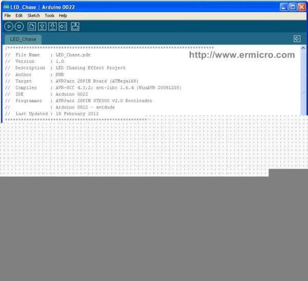
Now let’s start with the Arduino sketch first version of the LED Chasing Effect:
/*****************************************************************************
//  File Name    : LED_Chase.pde
//  Version      : 1.0
//  Description  : LED Chasing Effect Project
//  Author       : RWB
//  Target       : AVRJazz 28PIN Board (ATMega168)
//  Compiler     : AVR-GCC 4.3.2; avr-libc 1.6.4 (WinAVR 20081205)
//  IDE          : Arduino 0022
//  Programmer   : AVRJazz 28PIN STK500 v2.0 Bootloader
//               : Arduino 0022 - avrdude
//  Last Updated : 18 February 2012
*****************************************************************************/
byte LEDPin[]={0,1,2,3,4,5,6,7};
char LEDDirection=1;
char LEDOn=0;
unsigned int LEDDelay;

void setup() {
  // Set the digital PIN (0-7) to the Output Mode
  for (byte count=0; count <= 7; count++) {
    pinMode(LEDPin[count],OUTPUT);
  }
}

void loop() {
  // Turn off all the digital Output (0 - 7)
  for (byte count=0; count <= 7; count++) {
    digitalWrite(LEDPin[count],LOW);
  }

  // Turn ON one LED
  digitalWrite(LEDPin[LEDOn],HIGH);

  // Changed to the next LED
  LEDOn += LEDDirection;

  // Change the direction when reach 0 or 7
  if (LEDOn >= 7)
    LEDDirection=-1;
  if (LEDOn <= 0)
    LEDDirection=1;

  // LED Chasing Delay
  LEDDelay=analogRead(0);  // Select Analog PIN 0 for the Trimpot Input
  delay(LEDDelay);
}

/* EOF: LED_Chase.pde */
The program start with the variable declaration, where we connect the LED on pin 0 to 7 to the Arduino board digital output port. Next inside the setup() function we change the digital pin to the output mode (default is input mode) by using the pinMode() function.
After called the setup() function on the program execution, next the Arduino library will call the loop() function continuously; therefore we put the LED chasing effect algorithm together with the analog input reading inside this function.
// LED Chasing Delay
LEDDelay=analogRead(0); // Select Analog PIN 0 for the Trimpot Input
delay(LEDDelay);
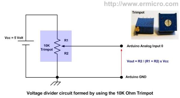
The trimpot will function as the voltage divider circuit and supply the varying voltage input (0 to 5 volt) to the Arduino board analog input 0.
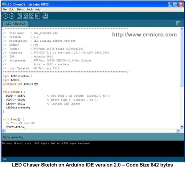
After compiling the LED chasing program we get about 1236 bytes of the Intel HEX code size (a binary file format used to program the microcontroller), the following is the slim Intel HEX code (842 byte) version of the LED chasing program using a “Non Arduino” approach of manipulating the digital output port.
/*****************************************************************************
//  File Name    : LED_Chase02.pde
//  Version      : 2.0
//  Description  : LED Chasing Effect Project
//  Author       : RWB
//  Target       : AVRJazz 28PIN Board (ATMega168)
//  Compiler     : AVR-GCC 4.3.2; avr-libc 1.6.4 (WinAVR 20081205)
//  IDE          : Arduino 0022
//  Programmer   : AVRJazz 28PIN STK500 v2.0 Bootloader
//               : Arduino 0022 - avrdude
//  Last Updated : 18 February 2012
*****************************************************************************/
byte LEDDirection;
byte LEDOn;
unsigned int LEDDelay;

void setup() {
  DDRD = 0xFF;             // Set PORT D as Output (digital 0 to 7)
  PORTD= 0x00;             // Reset PORT D (digital 0 to 7)
  LEDOn= 0x01;             // Initial LED Chaser
  LEDDirection=0;
}

void loop() {
  // Turn ON one LED
  PORTD=LEDOn;

  // Change the direction when reach 0 or 7
  if (LEDDirection == 0) {
    LEDOn=LEDOn << 1;       // Shift Left 1 Bit
    if (LEDOn >= 0x80) LEDDirection=1;
  } else {
    LEDOn=LEDOn >> 1;       // Shift Right 1 Bit
    if (LEDOn <= 0x01) LEDDirection=0;
  }

  // LED Chasing Delay
  LEDDelay=analogRead(0);  // Select Analog PIN 0 for the Trimpot Input
  delay(LEDDelay);
}

/* EOF: LED_Chase02.pde */
By using direct port manipulation we could get more slim code compared to the first version. Inside the setup() function we use the DDRD register on AVR ATMega168/328 microcontroller to set the PORTD I/O mode (digital pin 0 to 7).
DDRD = 0xFF; // Set PORT D as Output (digital 0 to 7)
PORTD= 0x00; // Reset PORT D (digital 0 to 7)
The 0xFF is the HEX notation of 255 in decimal notation or “1111 1111” in binary notation. By assigning the binary “1111 1111” to the DDRD register we instruct the AVR ATMega168/328 microcontroller to change the PORTD mode to the output mode.
On this version we use the “shift left” and “shift right” bit manipulation operator algorithm to achieve the same LED chasing effect as shown on the first version. The bit manipulation shift operator worked by shifting 1 bit to the left or right at the time as shown on this following picture:
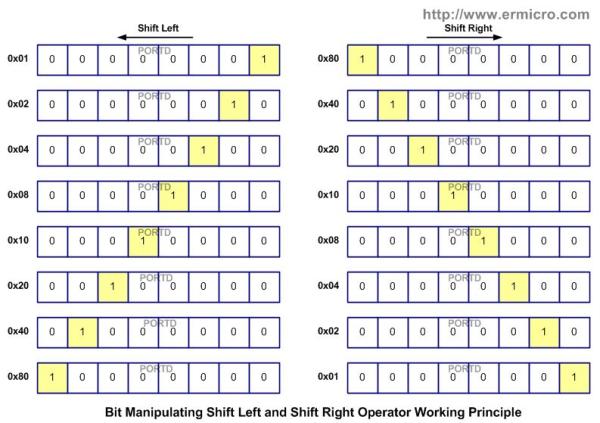
By shifting one bit at the time (left or right) we could create the LED chasing effect as we expecting instead of just turn OFF all the LED and turn ON one a LED as shown on the first code. The following C code shows the differences between these two algorithms:
The first version:
// Turn off all the digital Output (0 - 7)
for (byte count=0; count <= 7; count++) {
  digitalWrite(LEDPin[count],LOW);
}

// Turn ON one LED
digitalWrite(LEDPin[LEDOn],HIGH);

// Changed to the next LED
LEDOn += LEDDirection;
The second version:
 // Turn ON one LED
 PORTD=LEDOn;

 // Change the direction when reach 0 or 7
 if (LEDDirection == 0) {
   LEDOn=LEDOn << 1;       // Shift Left 1 Bit
   if (LEDOn >= 0x80) LEDDirection=1;
 } else {
   LEDOn=LEDOn >> 1;       // Shift Right 1 Bit
   if (LEDOn <= 0x01) LEDDirection=0;
 }
As the result, by using the second algorithm we could get efficient code and much more small Intel HEX code size to be loaded into the AVR microcontroller flash RAM.
The AVR Studio IDE
On the last example we will use a full C code on the Atmel AVR Studio to program this LED chasing project and I used the same “arduino style” function i.e. setup(), loop(), and analogRead() functions to make it easier to understand. The complete LED chasing project program is shown on this following C code:
//***************************************************************************
//  File Name    : LED_Chase03.c
//  Version      : 3.0
//  Description  : ACRJazz 28PIN AVR ATMega168 Demo Program
//  Author       : RWB
//  Target       : AVRJazz 28PIN Board (ATMega168)
//  Compiler     : AVR-GCC 4.5.1; avr-libc 1.7.1 (AVR Studio 5 ToolChain)
//  IDE          : Atmel AVR Studio 5.0.1223
//  Programmer   : AVRJazz Mega168 STK500 v2.0 Bootloader
//               : AVR Visual Studio 5.0.1223, STK500 programmer
//  Last Updated : 18 February 2012
//***************************************************************************
#define F_CPU 16000000UL      // AVRJazz 28PIN Used 16MHz
#include <avr/io.h>
#include <util/delay.h>

// Define byte to unsigned char
typedef unsigned char byte;

// Delay Function Implementation for avr-libc 1.7.1
void delay(unsigned int __ms)
{
  while(__ms--) {
    _delay_us(450);           // 2 x 450us for emulating 1 ms delay
    _delay_us(450);
  }
}

// Analog Read Function Implementation
unsigned int analogRead(unsigned char __anPort) {
  // Disable digital input on __anPort
  DIDR0 |= (1 << __anPort);

  // Select ADC Channel using ADMUX Register on ATMega168
  // Use internal Voltage Reference (REFS1=0 and REFS0=0)
  // ALAR bit is 0 for Right Justified Result
  ADMUX=__anPort;

  // Start conversion by setting the ADSC bit on ADCSRA Register
  ADCSRA |= (1 << ADSC);

  // Wait until convention complete ADSC=0 -> Complete
  while (ADCSRA & (1 << ADSC));

  return ADCW;             // Return the ADC Value
}

// Start the C Main Function
void main(){
  setup();                 // Call the setup() function

  // Enable the ADC Peripheral using ADCSRA Register on AVR ATMega168
  // ADC Prescaler: 128 (ADPS2=1, ADPS1=1, and ADPS0=1)
  ADCSRA = (1<<ADEN) | (1<<ADPS2) | (1<<ADPS1) | (1<<ADPS0);
  ADCSRB = 0x00;           // Free Running Mode ADC

  for(;;) {
    loop();                // Call the loop() function
  }
  return 0;
}

// Start the LED_Chase02.pde program on Arduino IDE
byte char LEDDirection;
byte char LEDOn;
unsigned int LEDDelay;

void setup() {
  DDRD = 0xFF;             // Set PORT D as Output (digital 0 to 7)
  PORTD= 0x00;             // Reset PORT D (digital 0 to 7)

  LEDOn= 0x01;             // Initial LED Chaser
  LEDDirection=0;
}

void loop(){
  // Turn ON one LED
  PORTD=LEDOn;

  // Change the direction when reach 0 or 7
  if (LEDDirection == 0) {
    LEDOn=LEDOn << 1;      // Shift Left 1 Bit
    if (LEDOn >= 0x80) LEDDirection=1;
  } else {
    LEDOn=LEDOn >> 1;      // Shift Right 1 Bit
    if (LEDOn <= 0x01) LEDDirection=0;
  }

  // LED Chasing Delay
  LEDDelay=analogRead(0);  // Select Analog PIN 0 for the Trimpot Input
  delay(LEDDelay);
}

/* EOF: LED_Chase03.c */
From the LED_Chase03.c program listing above you could clearly see that the C code inside the setup() and loop() functions is similar to the LED_Chase02.pde in the Arduino IDE. On the C code version in the AVR Studio (I used version 5) we add the necessary include, definition, typedef, and functions in order to make the setup() and loop() functions work properly.
![]()
By using a full C code on the Atmel AVR Studio we could significantly reduce the HEX size to 346 bytes compared to the HEX code produced by the Arduino library on our second version of the LED chasing program. For detail information of how to use the analog peripheral on the Atmel AVR microcontroller you could read this following article “Analog to Digital Converter AVR C Programming”.
I hope this small project will enlighten your embedded system knowledge and encourage you to learn more about the embedded system world.
Source: The LED Chasing Effect Project using Atmel AVR Microcontroller