Loucetios™ is a state-of-the-art, self-configuring lighting control system solution for bedrooms, offices and perimeter areas. Under automatic operation, the system senses luminosity inside and outside a room, controls the angle of the blinds and dims the lamps to maintain a prescribed level of illumination inside the room. The system also provides the user with 4 pre-programmed ambience settings that can set the tone of the room with just a button press. Loucetios™ is an environmentally friendly system that saves energy by keeping unoccupied rooms unlit and maximizing the use of available natural light. In the long-run, Loucetios™ provides control solutions that reduce energy costs and extend lamp life.
High level Design
Rationale
The driving force behind the idea of our project stems from the premise that Engineering is about harnessing nature to simplify our lives. Initially, we considered building an automation system to control access and illumination of a building through telephone access, thus allowing a user to remotely lock or unlock doors, close windows or switch lights on or off. However, after speaking with Professor Land about this idea we realized that developing such a system would entail many problems as phone lines are not available in the lab. We decided to modify the design and settled on a fully-automated lighting control system we call Loucetios™, after the Celtic god of Light.
Operation
Loucetios™ is a system that automatically controls the light in a room based on room occupancy, lighting conditions and user objectives by controlling the intensity of lighting inside and the amount of external light coming into the room. The innovative “floating” mode, operates under the energy-saving objective. The user defines a desired level of illumination and sets the system on floating mode. Loucetios™ will keep that level of illumination in the room prioritizing the least energy-expensive decision. When sunlight outside decreases, the blinds will be further opened and only until they can’t be opened will the system turn on lights inside the room.
For the user’s comfort, four pre-programmed settings are available.
• Bright day
On a bright day, one can open up all blinds letting plenty of natural sunlight in and turning off the lights to save energy.
• Privacy
The Privacy setting sets a medium level of illumination while closing all blinds, providing comfort and visual security to the user.
• Intimacy
The Intimacy setting is perfect to set a romantic ambience; combining the privacy of closed binds with low lights.
• Sleep
Turns off all lights and closes all blinds so that the user can rest peacefully.
These settings are provided as factory defaults but any arrangement can be re-programmed by the user. Please refer to the Pushbuttons section for button assignments and operation details.
Logic Structure
The central element of the system is the ATMEL Mega32 8-bit Microcontroller. It continually takes in information from the Infrared Sensors and the Light Sensors to make decisions on the opening of the blinds and the intensity of the light bulb.
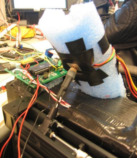
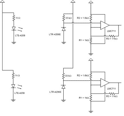
Infrared Sensors
The Infrared Sensors, mounted on the doors of the room, communicate to the microcontroller when they are toggled, indicating that somebody passed through the door. Depending on the direction of movement, the microcontroller determines if someone came into or left the room. The microcontroller keeps count of the people in the room and when nobody is in, the Sleep setting is activated.
light sensors
The light sensors are two photo-resistors mounted inside and outside the room. Each is connected to the microcontroller’s Analog-to-Digital Converter to provide a numeric interpretation of the amount of light inside and outside the room. The light sensors, coupled with the light dimming circuit described below, result in a feedback loop that permits automatic control of the system.
The Pushbuttons are implemented through bank of switches that communicate to the microcontroller when they are toggled, indicating that the button was pressed. The button presses are used by the microcontroller to determine whether it should operate the blinds and ligth automatically or whether it should set the ambience defined by the setting the user requests.
The original objective of the project was to electronically control the dimming of the light by switching it on and off repeatedly at a higher frequency than the AC line. However, due to unforeseen safety issues with the circuits involved, we decided to mechanically control a commercially-available Lutron® dimmer. The microcontroller controls a unipolar stepper motor that pulls the sliding interface of the Lutron® device. If let go, the sliding interface is pulled back by an elastic mechanism mounted contrary to the movement the motor provides.
Finally, the blinds are controlled by the microcontroller through another unipolar stepper motor that rotates the shaft that changes the angle of the blinds.
Sub-systems have different power supply requirements, however, the whole system runs from two 12V, 2.5 A power supplies.
Legal Issues
Considering that lighting control systems are “the next big thing” for energy saving, there are many companies that actually manufacture similar products. We tried to make product as competitive as possible by trying to comply as much as possible with California’s new energy code (Title 24) that significantly impacts lighting in new and remodeled homes. Just to provide some info, beginning October 2005, all new and remodeled homes must incorporate energy efficient lighting and controls. Depending on the room, these include:
Dimmers
Occupancy Sensors
Must be certified Title 24 compliant
Manual-on/automatic-off (can also be turned off manually)
Must turn off automatically in 30 minutes
Cannot be locked in a permanent “on” state
High efficacy lights – fluorescent, compact fluorescent (CFL) or high-intensity discharge (HID) lamps
Fluorescent, CFL, and HID lights must not have a medium screw base socket
Lamps rated 13 watts or greater must have an electronic ballast.
Though we did not have time nor money to work on the ballast, we think that all other points were covered.
Furthermore, RS-232 was implemented for communicating between the Mega32 and the Computer terminal. Other than those, after a reasonable search for such items, we really didn’t find infringement of any existing patents, trademarks or copyrights.
The IEEE Code of Ethics describes the professional standards all Electrical and Electronic Engineers are expected to abide by. The full code is shown below, with a description of how each section was related to our project experience.
1. To accept responsibility in making decisions consistent with the safety, health and welfare of the public, and to disclose promptly factors that might endanger the public or the environment;
Our product does not pose any hazards or safety issues to the consumer. We have all the wires for the circuits and power supplies covered with electric tapes to inhibit any unintentional contact with human skin. The light dimming module (provided by Lutron™) was uncovered to build the control system and can cause shock if touched. However, we covered the module with electric tape such that no one can pierce their finger through (unless they really want to).
2. To avoid real or perceived conflicts of interest whenever possible, and to disclose them to affected parties when they do exist;
There was no other lab group working on the same or anything similar to our project, and hence, there were no conflicts of interest.
3. To be honest and realistic in stating claims or estimates based on available data;
We did not manipulate or exaggerate our results or data in any form. We have disclosed all the codes and reference pictures to support our arguments made in the lab report. All costs incurred and prices of components are listed as per instructions and are true and accurate.
4. To reject bribery in all its forms;
Bribery… eh?
Abhijeet: Yo Marcelo, didn’t Eric just buy a Kawasaki?!?!?
5. To improve the understanding of technology, its appropriate application, and potential consequences;
Our project used various technologies of which our group members were not familiar with at the inception. We made sure we used the technologies for its appropriate applications. We have also made our best effort at communicating what we designed and how it should be used.
6. To maintain and improve our technical competence and to undertake technological tasks for others only if qualified by training or experience, or after full disclosure of pertinent limitations;
We designed and built the project solely for our interests and the course purposes. This was a great project experience and we definitely learnt a lot.
7. To seek, accept, and offer honest criticism of technical work, to acknowledge and correct errors, and to credit properly the contributions of others;
Our primary source of criticism and contribution was Prof. Bruce Land to whom we shall remain ever indebted. NB: He has been referenced (and ranked first) in our reference list.
8. To treat fairly all persons regardless of such factors as race, religion, gender, disability, age, or national origin;
Our group diversity shows how we embrace and appreciate diversity in the workplace!
9. To avoid injuring others, their property, reputation, or employment by false or malicious action;
We did not take part in any of the above mentioned malicious activities.
10. To assist colleagues and co-workers in their professional development and to support them in following this code of ethics;
Parts List:
| Qty | Item | Subsystem |
Price
|
Total
|
Source/Vendor |
| 1 | Blinds | Blinds |
$ 6.00
|
$ 6.00
|
E-Bay |
| 1 | PF35T-48L4 Motor | Blinds |
$ 1.00
|
$ 1.00
|
Lab |
| 0.25 | Solder Board | Blinds |
$ 2.50
|
$ 0.63
|
Lab |
| 1 | ULN2003AN Darlington Array | Blinds |
$ 0.64
|
$ 0.64
|
Digikey |
| 1 | Lamp & bulb | Dimmer |
$ –
|
$ –
|
Previously Owned |
| 1 | Lutron Incandescent Dimmer | Dimmer |
$ –
|
$ –
|
Previously Owned |
| 1 | Scanner Carriage Assembly (tracks) | Dimmer |
$ –
|
$ –
|
Previously Owned |
| 1 | Scanner Motor | Dimmer |
$ –
|
$ –
|
Previously Owned |
| 0.25 | Solder Board | Dimmer |
$ 2.50
|
$ 0.63
|
Lab |
| 1 | ULN2003AN Darlington Array | Dimmer |
$ 0.64
|
$ 0.64
|
Digikey |
| 1 | LM340T5 Voltage Regulator | IR |
$ 0.42
|
$ 0.42
|
National SemiConductor |
| 2 | LMC7111 OpAmp | IR |
$ 1.39
|
$ 2.78
|
Jameco |
| 2 | LTE-4208 IR Transmitter | IR |
$ 0.15
|
$ 0.30
|
Digikey |
| 2 | LTR-4206E IR Reciever | IR |
$ 0.24
|
$ 0.48
|
Digikey |
| 0.5 | Solder Board | IR |
$ 2.50
|
$ 1.25
|
Lab |
| 2 | Yellow LED | IR |
$ –
|
$ –
|
Lab |
| 2 | CL905L Photoresistor | Light Detection |
$ –
|
$ –
|
Lab |
| 1 | Custom PC Board | Main |
$ 5.00
|
$ 5.00
|
Lab |
| 1 | Mega32 | Main |
$ 8.00
|
$ 8.00
|
Lab |
| 1 | RS232 connector | Main |
$ 2.00
|
$ 2.00
|
Lab |
| 1 | RS232 driver | Main |
$ –
|
$ –
|
Sampled from Analog Devices |
| 2 | 12V, 2.5A Power Supply | Power Supply |
$ 5.00
|
$ 10.00
|
Lab |
| 2 | 2N3904 Transistor | Power Supply |
$ –
|
$ –
|
Lab |
| 2 | Adapters | Power Supply |
$ –
|
$ –
|
Lab |
| 0.5 | Solder Board | Power Supply |
$ 2.50
|
$ 1.25
|
Lab |
| 2 | TIP-31 Transistor | Power Supply |
$ –
|
$ –
|
Lab |
| 2 | Trimpot Variable Resistors | Power Supply |
$ –
|
$ –
|
Lab |
| 1 | Noodle Foam Tube | Structure |
$ 1.00
|
$ 1.00
|
Wal-mart |
| 0 | Wood | Structure |
$ –
|
$ –
|
Scrounged |
| 2 | 4-button bank | User Interface |
$ –
|
$ –
|
Lab |
| 1 | Solder Board | User Interface |
$ 2.50
|
$ 2.50
|
Lab |
| Total |
$ 44.51
|
||||
For more detail: Lighting control system Using ATMEL Mega32