Introduction
Sound bite
Our project is a karaoke recording machine which is capable of removing the voice component of a music file and storing the users singing voice with the background music to an external compact flash memory. It can also be used as a stand-alone voice recorder.
Summary
Our Karaoke machine has 6 modes. It also works as a digital voice recorder.
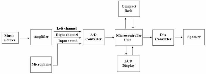
In the recorder mode, a musical file is read from an iPod. The vocal in the music can be removed. The remaining background music is added to the recorded sound signal acquired by a microphone. The playback sound therefore consists of the original music and the recorded sound. In order to have high quality sound, a relatively high recording speed is required, say 20KHz. An external serial mutli-channel ADC is used to extract the music signal. Considering the size of data, the local microcontroller memory does not have enough space to store such a big file, therefore an external storing device, like a memory flash card, must be used.
Motivation
The motivation of doing this project is to implement the ongoing research project under Professor Sergio Servettos group.
High-Level Design
Rationale and sources of your project idea
The rationale of the Karaoke machine is mainly for entertainment. The design idea also came from a research project under Professor Sergio Servetto’s group. By making some modifications we can increase the recording rate to be as high as megahertz.
Background
The method of removing vocal inside a song is to subtract the left channel from the right channel, or vise versa. This idea is based upon the fact that, during stereo recording, the singer is usually placed in the middle of the left and right microphone. Most instruments, however, are not. The result is that the singer’s voice is the same in the right and left channel, while majority of the instrumental sounds are slightly different in two channels. By subtracting the left and right channel, the vocal will be removed and the music shall remain. This is by no means a perfect technique because the assumption about the singer might not be true in some cases. And due to the echoes, the vocals cannot be completely removed, some “ghostly” sound always remain in the background. In addition, typically the bass instruments, such as drum, are usually placed in the middle as well. By using the method described above, the bass component of the music would be reduced as well. One possible way to solve this issue is to attach a low-pass filter to one of the input and leave the other channel alone. Due to time constraints, we did not implement the filter.
Logical structure
Specifications:
- Recording rate: 10kHz
- Memory: 96MBytes
- Recording time: 160 minute
Functions:
- Mode 0: Playback a song without any modifications, no recording
- Mode 1: Playback a song without vocal in it, no recording
- Mode 2: Playback a song with vocal and singer’s voice and record it into the external memory
- Mode 3: Playback a song without vocal and record it into the external memory
- Mode 4: Removing the vocal part of a song and storing the users singing voice with the background music to an external compact flash memory.
- Mode 5: Recording user’s voice into compact flash memory, no music
- Mode 6: Direct reading from memory
Standards
To record sound onto an external memory device, the format of that specific device needs to be known. For this project a compact flash will be used. Therefore, the IEEE standard of the flash drives format needs to be investigated. In addition, the method to communicate between the microcontroller and the drive should follow certain protocols.
Patents, copyrights and trademarks
The original record labels hold the copyright to the music we have used. We are not using them for commercial purpose.
Hardware
Karaoke Part
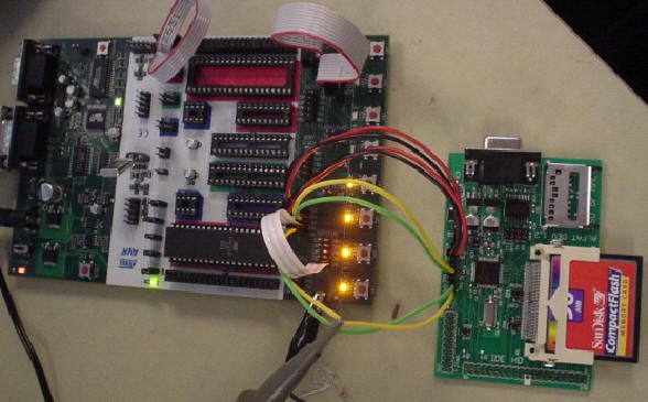
The hardware work involved in the Karaoke part mainly consists of two parts: ADC part and DAC part. The board layout is the shown as follows:
1. Music sources
- A music file from iPod including left and right channels
- Voice from microphone
The configurations of phone jack for microphone and speaker are as follows:
| Microphone | Stereo speaker | |
| Tip | Single | Left channel |
| Ring | Power | Right channel |
| Sleeve | Ground | Ground |
Therefore three channels of signals, which are left channel, right channel and voice channel, are fed into a multi-channel ADC at the same time.
2. ADC — MCP3204
MCP3204 is a ADC chip with 4 input channels and serial output which has 12 bit resolution. Given a 5V reference, the smallest detectable voltage change is 1.22 mV. The noise level in the circuit is already significantly higher than this value. However, other parts of the circuit limited the use of all 12 bits. Realistically, only the most significant 8 bits of the ADC output can be used. Since the analog output of Ipod and microphone are relatively low, in the 100mV range, some pre-amplifying circuitry needs to be constructed before A/D conversion. In addition, all the audio sources contain positive and negative amplitudes. In order to convert the negative amplitudes, a DC shift needs to be provided.
The circuit designed to accomplish the aforementioned goals is a simple op-amp that utilize both the inverting and non-inverting input end. The resulting output signal is generated according to the following equation:
- For left and right channels: R1=10kohm, R2=100kohm, Rx=50kohm, Ry=3khom, Gain=10
- For voice channel: R1=2kohm, R2=10kohm, Rx=10kohm, Ry=10kohm, Gain=5
The resistor values are carefully selected so that the DC bias is 2.5 V and the peak-to-peak value of Vout is around 4V. 4V is selected here because occasional high amplitudes in the original input might cause the output to clip if the gain is too large. A relatively small gain could reduce the occurrence of such event.
During the testing process of the ADC circuitry, three ADC chips stopped working after a few rounds of initial testing. This caused great frustration because to continue the work, a new ADC needs to be purchased and shipped by the vendor. One possible cause for this could be that the original amplifying circuitry used 5V power supply. Although the output of the amplifier is calculated to be within 1V to 4V, it could go below zero and cause damage to the ADC chip. A more critical mistake was that the analog ground and digital ground pin of the ADC are connected to grounds of two separate systems. After connecting those two grounds, the ADC chip did not fail again. The noise level also dropped dramatically.
3. DAC — DAC0832
According to the datasheet two op-amps are connected to the output of DAC0832.
Since this DAC has a current output, the first op-amp is used to convert current to voltage. The second one is for DC shifting. So the output can be oscillating between positive and negative as real audio signals. The final output voltage is calculated according to this equation:
For details please read the datasheet
4. Speaker
A speaker is connected directly to the output of the above DAC. Since the sound is playback at relatively good quality, no low pass filter is used.
Note: Please refer to the bread board layout in appendix
Memory part
ALFAT is a full FAT file system precompiled and programmed on a very small but powerful 32-bit processor chip, LPC2114 ARM processor from Philips. ALFAT requires very few external components to run. For communication, a simple microcontroller with UART, SPI or I2C can be used. Therefore, Mega32 MCU used in lab can be used with the ALFAT chip since it supports both UART and SPI. In addition, ALFAT implements two modes for communication, the first one is the text mode, which is a very easy text based commands that are very similar to DOS operating system. The second mode is framed mode, which is based on data packets, and is more suited for professional applications.
Software
Karaoke Part
LCD & Button update
A LCD is used to display the current mode of the karaoke machine. One push-button is used to change the mode. When pressed, the karaoke mode will cycle through all possibilities. The calling rate of LCD and button update routine are relatively slow so that they don’t affect the adc and memory operation significantly.
ADC (SPI)
The ADC chip we purchased has a built-in SPI interface. Therefore, the microcontroller needs to use the SPI port to communicate with the ADC. During SPI interfacing, one device is designated as the master, while the other one is the slave. ADC is the the slave device. The ADC chip has four pins associated with the SPI interface, so does ATMEGA32. For ADC, CS is the chip select signal which turns the it on when low. CLK is the reference clock signal. For MCP3204, the maximum frequency allowed for the CLK signal is 2 MHz, operating at 5V. Din is the input pin which controls the ADC to convert certain input channels. Dout is where ADC sends out the converted digital result. Initiating communication with the ADC is done by bring the CS line low. If the device was powered up with the CS pin low, it must be brought high and back low to initiate communication. The first clock received with CS low and Din high will constitute a start bit. The SGL/DIFF bit follows the start bit and will determine if the conversion will be done using single-ended or differential input mode. The next three bits (D0, D1 and D2) are used to select the input channel configuration. The device will begin to sample the analog input on the fourth rising edge of the clock after the starting bit has been received. The sample period will end on the falling edge of the fifth clock following the start bit.
Once the D0 bit is input, one more clock is required to complete the sample and hold period. On the falling edge of the next clock, the device will output a low null bit. The next 12 clocks will output the result of the conversion with MSB first. The entire operation cycle is illustrated in figure 10 below.
The SPI port of ATMEGA32 consists of 4 pins, PORTB.1-4. The are named MOSI(master out slave in), MISO(master in slave out), SCK and SS, which will be connected to Din, Dout, CLK, and CC, respectively. MOSI and MISO are controlled by the a function in the spi.h library. The function, unsigned char spi(unsigned char data), sends out the input argument through MOSI and collect the return value through MISO. One slight problem with this function is that the transmitted and received package are always 8-bit long. To solve this, some “leading zeros” are sent before the starting bit. The drawback for this scheme is that unnecessary clocks cycles are used, which slows down the sampling rate.
The control register for the SPI is called SPCR and SPSR. They’re used to enable the SPI, set up the clock rate, clock phase, and master/slave mode.
A dedicated ADC acquisition function is written to perform adc conversions. Based on the mode selected by the user, the acquisition routine will send out different channel select to the ADC. This function is called at a fixed rate by a interrupt service routine. The ISR used here is the timer0 compare interrupt. Clock has been scaled down to 250kHz by setting TCCR0 to 0x0B. OCR0 is set to 22 so that the interrupt occurs roughly every 100 s. This provide a sampling rate of 10kHz.
Memory Part
For our project, we used the UART interface to communicate between the MCU and the ALFAT chip because SPI interface is more complex, and we havent had exposure to it during the labs. In UART mode, UART_TX pin is used to send data to the microcontroller and UART_RX pin to receive commands from the microcontroller. The default baud rate for UART is 9600 and it is 8 bit with no parity and 1 stop bit, but the baud rate is changeable through the internal command. CTS and RTS lines must be used to insure not loss of any data. CTS pin is input to ALFAT and when it is high ALFAT will not send data and will wait for it to go low. CTS should be high as long as possible to not slow down ALFAT. RTS pin is output from ALFAT and it is set high when ALFAT 256 byte FIFO is full.
![]()
We used the frame mode since ALFAT has an internal Commander that follows orders sent by the host through the chosen Control serial executes the suitable process according to the order. The frame structure is shown in figure 12. The header consists of 3-bit function indicator and a 5-bit body length indicator. Body can be 0 bytes and up to 31 bytes. Body Length in the Header must be set according to this number of bytes. Checksum is simply the sum of header and all body bytes
ALFAT provides many functions which allows various communication with the compact flash, but the ones most vital to this project are:
- Change drive
- Read from opened file
- Write to opened file
- Open file
- Close file
- Set baud rate
These functions will be explained in detail below.
Change Drive:
![]()
The frame structure is shown in figure 13. The header is 0xE1 as defined above, and DriveChar can be A, B, C, and Z. Drive A indicates that ALFAT is connected to either MMC or SD card, drive B represents CF is connected as a master drive, drive C represents that CF is connected as the slave drive, and drive Z represents that no device is connected to ALFAT. Since we are using compact flash card, we set DriveChar to B.
Read from opened file:
Parts List:
| Item | Quantity | Unit price ($) | Total cost ($) |
| Power supply | 1 | 5 | 5 |
| Compact flash driver | 1 | 89.95 | 89.95 |
| Bread board | 3 | 6 | 18 |
| Mega32 | 1 | 8 | 8 |
| STK500 board | 1 | 15 | 15 |
| 14.7456MHz crystal | 1 | 1 | 1 |
| MCP3204 | 3 | 5.5 | 16.5 |
| DAC0832 | 1 | 1.47 | 1.47 |
| Total | $ 154.92 | ||
For more detail: Machine de Karaoke Using Atmega32