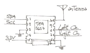
I’ve started to build a little FM radio with one of this cheap modules with a Phillip chip, the TEA5767. I will control it with a MSP430, probably I’ll use some kind of encoder to change stations and a potentiometer for the volume.
The TEA5767 is a single-chip electronically tuned FM stereo radio for low-voltage applications with fully integrated Intermediate Frequency (IF) selectivity and demodulation.Most of the information of this devices is from the datasheet and this app note.
The I2C-bus mode is selected when pin BUSMODE (PIN 3) is LOW. The serial interface use pin 1 as SDA and PIN 2 as SCL. The board is powered with 3.3V with VCC being PIN 5 and GND in PIN 6. PIN 10 is there to connect an external antenna (just a piece of wire) and PIN 7 and 8 are the audio outputs. Pins 4 and 9 are left unconnected.
First of all let me explain some basics concepts about FM radio receivers in order to understand how to configure the different settings this chip has. I might be oversimplifying some things here, I’m just writing what I’ve read and understood while searching information to use this thing so beware of mistakes!
For more detaiL: Making an FM radio-Part 1; the TEA5767

