Morse Code Alarm Clock Modification
(Almost) Trivial application of an AT90S2313 or ATtiny2313 in an alarm clock to change the alarm from “BEEP BEEP BEEP BEEP BEEP BEEP BEEP BEEP…” to “WAKE UP” in Morse code. This was designed in response to a request and is in daily use
Downloads (Updated 5 December, 2004)
AVR Studio Assembly Source: morclk041204A
AVR STudio Hex file: morclk041204A.hex
Overview
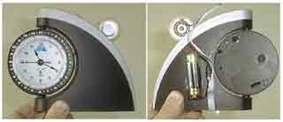
The speaker is mounted on the top edge and
the AA battery holder is glued to the back. Flat ribbon
cable is used for all the interconnections.
An inexpensive alarm clock was modified by installing a small circuit board inside the clock body and attaching some wires to the clock’s circuit board. The second AA cell needed to bring the voltage up to 3 volts for the micro controller is mounted on the back. The high impedance speaker was temporarily mounted on the top as I pondered where the best permanent location would be, and like many decisions that are delayed with the aid of a temporary fix, its still waiting final disposition.
Circuit
The 0.22 uf capacitors are ceramic monolithic.
The micro controller sleeps most of the time, consuming mere micro amps until it receives an interrupt. and wakes up, then, using timing loops, it generates timing for “WAKE UP” in Morse code. Interrupts provide a 2 kHz square wave on pins 14 and 15 that are 180 degrees out of phase with one another (when one pin is high, the other pin is low), which means that the speaker sees a square wave that is nearly 6 volts peak-to-peak (or 3 volts RMS since it is a square wave). The 100 uf capacitor in series with the speaker keeps it from drawing any DC power. Once the “WAKE UP” message has been sent, the micro controller goes back to sleep.
The digital inputs are pulled high with the chips’ weak internal pull-ups to minimize power dissipation. The speaker outputs are configured as outputs (I hope that is not a surprise).
The clock module runs from a single 1.5 volt AA cell. To raise the voltage to 2.7V or greater to run the AT90S2313, I added a second AA cell that only powers the AT90S2313.
The alarm signal is taken from one of the wires from the alarm clock module to the clock’s speaker. When the signal swings to ground, the 2N4401 in the alarm module sinks enough current to pull the interrupt pin low. The 39k resistor on the base of the 2N4401 sets the base current to (1.5V-0.7V)/39k = 20 micro amps. The weak pull-up on pin 6 supplies less than 85 micro amps when grounded, with 30 micro amps being typical, so the base drive is more than sufficient.
Notice that this transistor’s main function is to amplify the 1.5 V peak-to-peak signal from the alarm module to one that swings from ground to the micro controllers’ positive power supply. The 0.22 uf capacitor cleans up the signal on the collector so that the collector goes low when the alarm signal comes in and stays low for about 2 milliseconds after the last beep.
For more detail: Morse Code Alarm Clock using ATtiny2313 microcontroller

