Our final project is to build a multifunctional music box. This music box can generate different songs in different instrument sounds, i.e. piano, organ, by FM synthesis. The theme and harmony are in two different channels. Besides, the music box can also be electrical piano by which users can play their own music, the piano keyboard is implemented by infrared emitter and light sensor. There is also tutorial function which can teach users to play a sound stored in music box. Distance sensor to control music box switch. 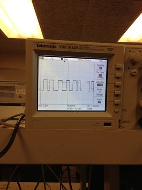
High Level Design
Rationale and Inspiration
Music synthesis is always a very interesting and enjoyable project of Microcontroller. Inspired by Lab 2 and Bruce’s random music box, we want to expend the basic function of traditional music box to a multi-function music box. Traditional music box often just has one song to play which lacks of user interaction. What we do in the final project is let users to choose the music and the instrument they like. Apart from that, users can even play their own music by our friendly user interface. The music box can also teach user to play a simple song. Our music box is very suitable for children to gain a basic interest in music.
Background Math
The distance sensor is the switch of music box. The output of the distance sensor is analog signal sent to Port A0. MCU get the result of ADC converter, comparing it with the default threshold. To ensure the ADC could sample fast enough to obtain the distance information with minimal latency, we set timer2 as compare match mode and use compare match ISR to get the ADC result. The interrupt time interval of timer2 is:
Remark:
- OCR2A=249, then timer2 has 250 sticks.
- The clock rate of MCU is 16MHz
- Prescalar of timer2 is set to 64, the time interval for timer2 stick is
We add time1 as time record variable and increase time1 once in ISR, checking the ADC value when time1 equals to 250. So the sample rate of distance sensor is 250ms.
Logic Structure
At the beginning, our user control are combined by distance sensor and user interface. Distance sensor reflects the distance between music box and user, music box will only produce music when distance is shorter than the threshold. Then the switch button can change the work mode. There are two work modes:
(1) Music Play Mode
Under this mode, the music box will automatically play the songs stored in the Microcontroller. The user interface made by infrared emitter and light sensor can change different parameter of the song including song itself, instrument and harmony. There is also a line as hold button. When hold function is chosen, even the distance between user and music box are longer than threshold, the music will keep playing. This function enables users to listen the music and do anything else at the same time. (2) Play Electrical Piano Mode Users can also change to Play Electrical Piano Mode to play their own music. It can generate the sound of basic range including 12 notes from C4 to B4. There are also a tutorial function which can teach users to play a simply song. The LED on each note will light up in order, by following this play order, users can play the song.
Hardware and Software trade off
1. Hardware:
To simple the process of signal result of distance sensor and increase accuracy, it’s better to use digital distance sensor instead of analog one. However, digital distance sensor costs much more than analog one and digital sensor need 8 ports on Microcontroller to receive the result. Besides, in our final project, accuracy doesn’t affect too much, so we decides to use analog distance sensor and use internal ADC of Microcontroller Mega1284 to realize AD converter.Software:
2. Software:
The main trade off of software is the choice of sound synthesis algorithm. Karplus-Strong physical synthesis is very suitable for microcontroller because of its simple algorithm, besides it can produce the sound a real instrument, however, it can only generate several notes since performance will be affected a lot by high frequency. FM synthesis may not generate sound as real as Karplus-Strong physical synthesis, but its frequency range is much larger which meets the requirements to play a whole song rather than just several notes. After serious consideration, we end up use FM synthesis.
Existing Patents/Copy Rights/Trademarks
Music synthesis is a very popular project on microcontroller since its implementation is very simple and feasible. There are projects based on different sound synthesis algorithm and the focuses of these projects vary a lot. Our project focus is to produce a multi-functional music box to enhance user experience. With infrared emitter and light sensor, user can control the music box by touch screen like interface. Apart from that, combining song play and piano play together with different mode and instruments will bring more fun and provide more personalization options. Some projects may similar to our project, but we don’t infringe on other copy rights or intellectual property, as we did not consult other projects for choosing a particular implementation method and we have no intention of patenting our design.
Hardware Design
In the final project, there are four main parts of the hardware design. First part is the infrared detector circuit and one push button as our user interface. Second part the distance detector circuit as the main switch of the system. The third part is PWM design in the MCU to generate the music box sound. The last part is 8 led to shown the status of the system.
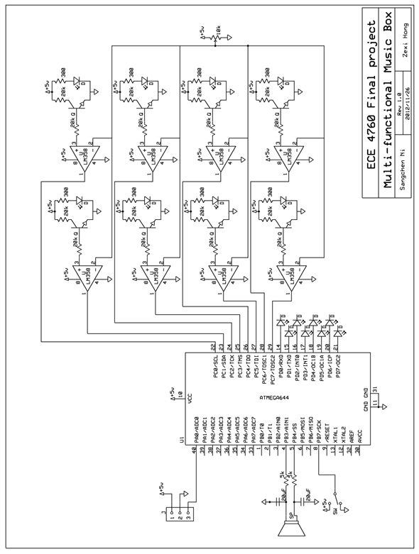
Infrared detector circuit
We use eight infrared emitters to irradiate directly on eight phototransistors, so that it can detect when fingers are between them and generate a sinc on the waveform. sing the circuit of Figure 4, the voltage of output will be lower when conducting the base and emitter of the phototransistor. To transform the waveform to a square sinc wave so that the MCU can detect pulse more easily.
When the voltage of pin.3 is higher than the voltage of pin.2, the pin.1 output 5 volt. When the voltage gets lower, and becomes lower than the pin.2, the pin.1 output zero.
With the 1M resistor set between the pin.1 and pin.3, there will be a little amount of positive feedback add to the pin.3. So the waveform of pin.3 will lag behind a little. This lagging behind will reduce the effect of noise on the waveform which may cause the output square wave unstable.
PWM To generate music sound by PWM, we set timer0 run as full rate and turn off overflow ISR to turn on fast PWM, OC0A output and OC0B output. The initialization set of PWM is 16 microsecond per PWM cycle sample time. In final project, we use two channel of PWM. The first one we used (OCR0A) is to generate the theme of the song at B3 port while the second one (OCR0B) which comes out at B4 port reflects the harmony of the song. These two PWM are put into the two channels of the speaker after low-pass filter. Low-pass filter
A low pass filter is needed to connect to the Port B3 (OC0A) and Port B4(OC0B) so that we can filter most of the wave of high speed PWM-based D/A signal and receive a sine wave based on the appropriate PWM output. We need a resistor that isn’t bigger than the input resistance of the speaker audio input (10 kohm), but isn’t too small that can load the port pin.
The RC time should between 2 to 10 times period of PWM. But we don’t wa
Parts List:
Name |
Price |
Quantity |
Total price |
Vendors |
White board |
$6 |
1 |
$6 |
4760 LAB |
Bread board |
$2.5 |
2 |
$5 |
4760 LAB |
Distance sensor |
$14 |
1 |
$14 |
Acroname |
Mega 1284 |
$5 |
1 |
$5 |
4760 LAB |
Custom board |
$4 |
1 |
$4 |
4760 LAB |
Speaker |
$0 |
1 |
$0 |
4760 LAB |
Flat jumper |
$1 |
20 |
$20 |
4760 LAB |
Switch |
$0 |
1 |
$0 |
4760 LAB |
Resistor |
$0 |
— |
$0 |
4760 LAB |
Capacitor |
$0 |
— |
$0 |
4760 LAB |
Infrared emitter |
$0 |
8 |
$0 |
4760 LAB |
Light sensor |
$0 |
8 |
$0 |
4760 LAB |
LED |
$0 |
8 |
$0 |
4760 LAB |
Battery box |
$0 |
1 |
$0 |
4760 LAB |
$58 |
For more detail: Multi-functional Music Box Using Atmega1284