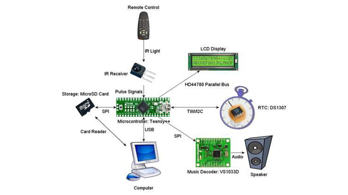
This Instructable will be about designing a music player from using various building blocks. You will understand the communication between the microcontroller, memory, computer, LCD display, RTC, IR remote, and the music file decoder. I will try my best to to teach you in a way so that you can design your own projects using the skills you learn, without blindly following instructions.
I know most of you will simply glance at this first page and maybe skim through the rest. This Instructable has 18 steps and 5 appendices, with about 90 files and pictures. I sincerely hope you explore all my efforts.
Every step will be accompanied by a demonstration of that particular building block working. The source code will be provided. I will post the debug output, pictures, screenshots, USB device and packet analysis, and logic analyzer waveforms. NOTE: if the images look too compressed, don’t worry, they are included inside my .ZIP files too.
To start off the project, set your goals. This will be a simple proof-of-concept music player. It will allow the user to load music as through USB as though it is a mass storage device, display the current song to the user, display the current time, set custom alarms for every day of the week, and allow the user to control it through a remote control. To accomplish these goals, you need:
* USB capable microcontroller
* LCD display
* Storage
* Sound output
* IR receiver and remote control (any)
This is the obvious overview, however, we also need a RTC (real time clock) to keep track of time using a backup battery, just in case the power goes out.
Note that with my collection of supplies, budget, and skills, I’ve decided to use a VS1033D decoder IC from VLSI Solutions, which integrates music file decoding and digital-to-analog output. So the item “sound output” in the above list expands into “decoder” and “speaker”
I will be using the following components during this Instructable (this is not a full part list, not even close, but these are major):
AT90USB1286 microcontroller (on a Teensy++ http://www.pjrc.com/store/teensypp.html ), datasheet is here: http://www.atmel.com/dyn/products/product_card.asp?part_id=3874
VS1033D music decoder http://www.vlsi.fi/en/products/vs1033.html on a breakout board http://www.sparkfun.com/products/8792
16×2 character LCD display, ST7066/HD44780 compatible, using 3.3V instead of 5V
DS1307 real time clock
Note that the entire circuit will run off 3.3V, if you are buying a Teensy or Teensy++, please buy http://www.pjrc.com/store/mcp1825.html and follow the correct procedures to solder it and use it (it involves a jumper). Please also note that you must also run the Teensy at 8 MHz instead of 16 MHz because of the reduced voltage.
I also hope that once you are done, you’ll be able to apply the skills you learn here with other microcontrollers and devices.
Before You Begin
Instead of giving you the whole schematics and source code and tell you to build the damn thing while showing pretty pictures, I will break down the building blocks of this project, and give you demonstrations of that particular “block” that you should perform in order to understand what is going on. Through this process you will learn how to diagnose problems and also how to use various techniques in other projects.
To get you started, I will make sure you know how to compile and upload a “hello world” program to the Teensy++. This code will show you how to output debug messages, which will be useful later.
Obviously you need an AT90USB1286 microcontroller for this, and since it’s hard to solder by hand, I choose to buy a Teensy++. http://www.pjrc.com/store/teensypp.html
This example is based on “USB Serial” on PJRC
http://www.pjrc.com/teensy/usb_serial.html
If you wish to learn more about communication with USB, please refer to my appendix “step” about USB.
Please refer to my appendix “step” about AVRs to figure out how to use makefiles and the GNU AVR toolchain.
Download the files attached. Run “make” to generate the .hex file. Upload the .hex file to the microcontroller. Open up a serial terminal to see the output. The baud rate shouldn’t matter since this is a fake serial port.
Provided below is the USB analyzer dump of the device and a sample packet of data, for those of you who wish to learn more about USB.
Note: I personally REALLY like using RealTerm as a serial terminal http://realterm.sourceforge.net/ , I will be posting screenshots of the terminal output whenever I can. I will also post logic analyzer screenshots, .logicsession files (can be opened with the Saleae Logic software http://www.saleae.com/logic/ ), and exported files whenever I can.
Some people have asked me about how to use stdio.h and printf (and similar streaming and formatting functions) on AVR microcontrollers, the following links are in the code comments:
http://www.nongnu.org/avr-libc/user-manual/modules.html
http://www.nongnu.org/avr-libc/user-manual/group__avr__stdio.html
Also since this is “before you begin”, go download Saleae Logic’s software, if I ever attach .logicdata files, you need the software to view it. http://www.saleae.com/logic/ , it’s in the downloads (version 1.1.14 is what I used) page, you can use it even if you do not own a Saleae logic analyzer. I will also try to include screenshots.
Storage with MicroSD Card
Most music players now have built-in flash memory. We are hobbyists who probably can’t solder those chips. We want something simple to use. A MicroSD card is perfect, and it’s easy to make your own MicroSD card socket that you can prototype with on a breadboard (see picture).
SD and MMC cards are easy to use because they provide a SPI (serial peripheral interface) interface that can be used to read and write data to and from the card. Please read the following resources to understand SPI and the SD card:
http://en.wikipedia.org/wiki/Serial_Peripheral_Interface_Bus
https://www.sdcard.org/developers/overview
http://elm-chan.org/docs/mmc/mmc_e.html
AT90USB1286 Datasheet section 17 http://www.atmel.com/dyn/products/product_card.asp?part_id=3874
If you don’t read the above three links, you will not know what I’m talking about next.
In short, the SPI bus is a bus where you place data onto the data lines (MISO and MOSI) one bit at a time, and the bit is sampled on the edge of a clock signal.
Our microcontroller has a dedicated SPI peripheral. By examining the above links I provided, we know the following facts:
Our microcontroller is the “master” and the SD card is the “slave”
The SD card uses SPI mode 0 (CPHA=0, CPOL=0), this means the clock signal starts low and the data input samples data when the clock transition to high
The maximum clock speed of the SPI bus
From the above information, we are able to initialize the dedicated SPI peripheral within the microcontroller. Refer to section 17 of the AT90USB1286 datasheet.
If you didn’t work out the obvious electrical connections you will need, here’s an explaination:
MOSI (Master Out Slave In)
The master refers to the device that generates the clock (the microcontroller), the SD card is the slave. Data on this pin travels from the microcontroller to the SD card. Also known as “DI”.
Connect the DI pin on the SD card to the microcontroller’s MOSI pin
MISO (Master In Slave Out)
Data on this pin travels from the SD card to the microcontroller. Also known as “DO”.
Connect the DO pin on the SD card to the microcontroller’s MISO pin
CS
Chip select, the SD card pays attention to the data traveling on the SPI bus when this pin is low, and ignores the data on the bus when this pin is high. This is also known as “SS”.
The CS pin on the SD card can be connected to any free pin on the microcontroller
SCK or SCLK or CLK
This is the serial clock pin,
Connect this pin on the SD card and microcontroller’s SPI clock in (called SCK in the datasheet)
The next step will take you through a step-by-step that shows you the basics of communicating to a SD card. As preparation, if you do not already have a good MicroSD card holder, then take some male pin headers with 0.1″ spacing, and solder it to a MicroSD card adapter, as shown in the pictures below. The steps to make this makeshift card holder is in my appendix.
Communicating with SD Card Example
Ensure that your microcontroller is operating at 3.3V by installing the 3.3V voltage regulator
http://www.pjrc.com/store/mcp1825.html
http://www.pjrc.com/teensy/3volt.html
Warning, if you read the SD card specifications I linked you in the previous step, you will realize that SD cards run at 3.3V, and thus, using the Teensy++ at 5V may damage your SD card (however, this is unlikely, but we like to be safe and rule out reasons for failure).
Make the wiring connections like in the diagram provided.
The code is provided in the attachment below. You should study the source code while examining the SD card specifications I’ve linked to in the previous step. This way, you can make the mental connections between the commands I’m sending and what they are in the specifications, and then understand what my code expects to receive verses what the specification says what I should receive.
A logic analyzer session file is also provided for you to look at. It will show you the electrical signal waveforms during SPI communication between the microcontroller and the MicroSD card.
FAT File System with MicroSD Cards
Your microcontroller can grab blocks of data from a SD card, great, but now all you have is blocks of raw data, which is not very useful. You need a file system to make these blocks of data useful.
http://en.wikipedia.org/wiki/File_system
The FAT file system is quite complex and so we will be using FatFs from Elm-Chan.org to help us.
http://elm-chan.org/fsw/ff/00index_e.html
FatFs is completely written in C and is platform independent, while designed so that it can be configured so it’s friendly with limited memory environments (such as microcontrollers). This makes it a perfect solution.
To integrate FatFs into your software project, simply have the files in place, compile “ff.c” (taken care of by the makefile), place the line
#include “ff.h”
into where ever you need to use FatFs API
Also you need to provide a “diskio” module so FatFs can interface with the SD card. “diskio” will contain various methods that uses SPI to allow FatFs to read and write data to and from the SD card.
Note that the SD card should be formatted FAT16. Use whatever operating system you are using to do that. Try not to use FAT32 or SDHC cards (or cards bigger than 2GB) because they don’t work with many DIY SD card solutions.
The next step in this instructable contains the demonstration source code for the Teensy++ that will read all the files on your SD card and display them through the serial terminal.
Reading a File from SD Card Example
Format the card as described in the previous step (you did read it, right? The format is FAT16 in case you need a reminder)
Create several text files and blank folders on the root of the card. Give the text files some content.
Insert the card into our makeshift MicroSD card holder.
Study the source code I’ve provided, it should read each file name and then output the contents of the file. Please refer to the FatFs API documentation while exploring the source code to understand how to iterate through files inside a directory, and how to open a file.
http://elm-chan.org/fsw/ff/00index_e.html
Compile the attached code and upload and watch the output inside the serial terminal. It should visit all the files in your SD card and then output them to the serial terminal.
USB Mass Storage with MicroSD
First, to understand the basics of USB (Universal Serial Bus), please read my appendix about USB.
Then, to understand USB mass storage
http://en.wikipedia.org/wiki/USB_mass-storage_device_class
http://en.wikipedia.org/wiki/SCSI
http://en.wikipedia.org/wiki/USB_Attached_SCSI
What I need you to understand is how the computer determines what kind of device is connected (so understand USB descriptors), and then understand that the computer will issue SCSI commands via USB to the microcontroller, and the microcontroller will execute those SCSI commands by communicating with the SD card. SCSI works directly on the raw memory of the SD card, without caring about the file system. It does not care about files, only bytes.
———————————————————————————————————
The AT90USB1286 is capable of full speed USB (not high speed!! keep this in mind as file transfer speeds will not be the best, plus our Teensy is only running at 8 MHz and the SPI clock is only at 4 MHz). To use its built-in USB, we have a few choices. Manually program an USB stack in C, or use the USB stack code provided by Atmel, or use LUFA (Lightweight USB Framework for AVRs).
We will use LUFA (version 101122 as of the time of me writing this), it’s open source and it’s design specifically for this particular family of AVR microcontrollers.
http://www.fourwalledcubicle.com/LUFA.php
Download and explore LUFA’s code, documentation, and examples.
We will utilize the the mass storage demonstration included in the LUFA distribution. However, that particular demo uses a dataflash IC instead of SD card. So here’s an example by Elastic Sheep which uses SD cards:
http://elasticsheep.com/2010/04/teensy2-usb-mass-storage-with-an-sd-card/
BUT WAIT THERE’S MORE! I have modified the files from the above link to work with the Teensy++ and updated it to use LUFA version 101122. See attached example package. As usual, simple compile and upload the code. Inside the package I’ve also included an entire description of the USB device dumped from an USB traffic analyzer. If this worked, then you have effectively just built a SD card reader out of a Teensy++, congrats.
The files sd_raw.c and .h are there to communicate with the SD card directly. SDCardManager is there to allow SCSI to access the SD card in a way that SCSI can work without caring what kind of memory it is working with (abstraction, SCSI is higher level). MassStorage handles most USB mass storage device functionality, and uses SCSI according to the commands received from the computer.
LCD Display Basics

We will be using a 16×2 character LCD display that is using HD44780 or is compatible with it. Make sure the LCD display runs at 3.3V, because we have configured our Teensy to run at 3.3V. If the LCD needs 5V, it obviously won’t have enough power.
This is the exact model I have used: http://www.sparkfun.com/products/9052
You can pick and choose the colour but make sure it’s HD44780 compatible and runs at 3.3V
I liked “white on black” because it’s readable at night but not disturbingly bright.
The significance of it being HD44780 compatible is because it’s common. Everybody knows how to use it. Here are several tutorials by simply searching for “HD44780 tutorial”
http://joshuagalloway.com/lcd.html
http://jallib.blogspot.com/2009/01/step-by-step-interfacing-hd44780.html
http://www.8051projects.net/lcd-interfacing/introduction.php
http://www.robotenthusiasts.com/page/index.html/_/tutorials/pic-microcontrollers/hd44780-lcd-r14
Notice how all those tutorials were identical?
Now grab the datasheet for the display (this is from SparkFun’s product page):
http://www.sparkfun.com/datasheets/LCD/ADM1602K-NSW-FBS-3.3v.pdf
The data is sent via a parallel bus, the data is placed onto the data pins, and sampled when the “E” pin is toggled.
Take notice of the timing diagrams on page 7. If we do a quick calculation, the Teensy at 8 MHz means the time it takes for one assembly instruction is 125 nanoseconds. The LCD communication code has taken this into account (look for where I’ve put “_NOP();”). Each command also take a minimum time to execute as well, as you will see.
Take notice of the commands listed on page 10, it will help you understand the initialization code later when you read the source code. Also as I’ve said before, each command takes a minimum time to execute, and the amount of time is listed here. Also we will not be reading any data from the LCD, only writing, this means the “read/write” or “R/W” pin can be connected to ground, meaning “write only”.
Look at the character table inside the datasheet, it’s almost the same as ASCII with a few small exceptions. This makes it easy to display text strings.
Also note that we will be using 4 bit mode to save pins and wires. The description of how 4 bit mode works is not exactly on the datasheet but the command called “function set” is what is used to enable 4 bit mode. Notice that 4 bit mode uses bits DB7 to DB4, and “function set” is designed so that DB3 to DB0 are not required to enable 4 bit mode.
To understand more about 4 bit mode, try reading this first
http://esd.cs.ucr.edu/labs/interface/interface.html
Basically, you send the most significant 4 bits first, and then the least significant 4 bits second. Once the LCD has been set to 4 bit mode, it always expects 2 data transfers, whereas while in 8 bit mode, it only expects 1 data transfer, this is why setting 4 bit mode must be done early, although the commands are designed so that it doesn’t have to be the first command.
The contrast is controlled by pin 3 on the LCD, I find using a 10 kilo-ohm trimmer potientiometer as a voltage divider input to pin 3 is the easiest method of controlling contrast.
The backlight LED will be controlled by our microcontroller. There should be a current limiting resistor in series so that the LED or our microcontroller GPIO doesn’t burn out.
The next step will be an example demonstration, which will also show you the wiring connections.
For more Detail: Music Playing Alarm Clock using Microcontroller AT90USB1286