If you’ve poked around the internets where electronics hobbyists collect, it is likely that you are acutely aware of our incontrovertible affinity for building timekeeping clocks. It is similarly unlikely that you have been able to evade the plenitude of nixie tube based projects. There is a reason for this.
Nixie tubes are cool. They have great aesthetic appeal with their difficult-to-photograph, warm orange glow, and dem curvy numerals. They add an organic je ne sais quoi to a hobby with ostensibly digital design cues. Further, they pose technical challenges in the way of producing and switching the ~175 V DC needed to light each tube element. And as far as I am aware, there are no new nixie tubes being produced; as such, procurement can be a challenge unto itself. My N.O.S. nixies came from Russia thru Ebay, and only 3 were duds. Incidentally the seller replaced those 3, FOC.
 Fortunately, not all nixie tube clocks are implemented the same. In fact, look around at all the schematics for nixie clocks, and you will realize there are more permutations in methodology than there are models of nixie tubes. This is how it should be. We ( DIY electronics people ) like to put our own spin on things.
- Single microcontroller design.
- Software based RTC.
- Software driven boost converter for ~175 V DC supply.
- Time, Date, and behavior configuration via USB
- Windows application for clock configuration.
- Time, Date, Temperature, and AC Power line frequency display.
The Name
Downloads
The Nixie Clock Communicator code can be found on GitHub here: https://github.com/pilotingpete/nixieClockCommunicator
An Electronics BOM – Please notify me of any errors: https://docs.google.com/spreadsheets/d/1ZhO8OGlxGMYI7I5BOQ9BeYuwDf4MAAcQkCAm8IlP1JA/edit?usp=sharing
The KiCad schematic and board files. Also, a collection of datasheets, and some logfiles from when I calibrated my prototype clock. Perhaps there are some other files in this archive that I thought were useful while I was working on this project too: https://docs.google.com/file/d/0B1CPUkh94AtmMmM5Y1NmeGttLWs/edit?usp=drive_web
Here is the current schematic in PDF in case you don’t have KiCad installed.
RTC
Four short years ago I posted about a method for building your own microcontroller based realtime clock. This is essentially a method to calibrate your xtal to more closely match real time, and some code to keep track of the time and date. The benefits of a uC based RTC include a reduction in components and everything that comes with that; increased reliability, cost reduction, real estate savings, &c. We can also achieve accuracy in timekeeping greater than that specified in stand alone IC RTC’s datasheets.
In the aforementioned post, we only discussed the theory and showed a proof of concept example. There were no software provisions for calendar with leap year, 12/24 hr format, etc. That is, the finishing touches to make a useful RTC for a clock were left out. This nixie clock builds upon the methods for coding your own RTC and shows the implementation to make a useful clock. This code could easily be recycled into any number of clock projects with LED, LCD, OLED, displays too.
The core RTC code can keep track of the time and date, account for leap years, and report the day of the week. One could expand this to take care of DST, but I go into detail about why I don’t in the previous post.
While designing the hardware for the clock I added a “zero cross detector” to the incoming AC power line. We can use this in lieu of the calibrated xtal to keep time – users choice.
USB Interface
For example, open a terminal to 56700 baud and type “celsius=1” and hit enter. This will set the clock to display the temperature on the Celsius scale. Setting this parameter to 0 would result in the Fahrenheit scale i.e. “celsius=0”.
If you were to type “hours?” the clock would reply with “Hours: nn” where nn is the currently displayed hours. There are also parameters for “showFreq”, “showDate”, showTherm; each of which are set to display its unique parameter value at the top of each minute or not. i.e. if you type “showtherm=1” then at the top of each minute the temperature will be displayed – in Celsius or Fahrenheit as previously discussed.
Below is a screenshot of the available commands. At the terminal type “help” and hit enter. The column labeled “command” shows you the available parameters to configure. “Set/Read” column suggests that you may set a value with ‘=’ and read the value with ‘?’. The “Low Lim” and “High Lim” columns show the range of acceptable values to input.
| USB Terminal Interface |
“getall” returns a csv line of all current parameter values. The order can be verified in the firmware.
- “ramtoeeprom” will store all current parameters to eeprom so that they are recalled after a total power removal. Time and date are excluded – view the firmware to confirm all parameters that get stored.
- “poke” returns the clock serial number – mine is S/N: 100; what will yours be?
- “pwrok”, “hvfeedback”, “battvoltage”, and “rectifiedac” return system voltages. Refer to the schematic for voltage points.
- “doecho” is a UART echo and is useful for typing at a terminal; it lets you see what you are typing. It is not so useful when using the NCC app and should probably be turned off i.e. “doecho=0”
- “nixiesleepstart” and “nixiesleepend” set the time that the nixies turn off and on at night. We dont need to burn up valueable nixie time while we are sleeping. If nixiesleepstart is 0, then they will never sleep and nixiesleepend is necessarily ignored.
- “toggleled” if set to 1 then the LED on PD7 will toggle at 1 Hz. Set to 0 and no more toggling – the LED will remain in its current state. It is neat, although power wasteful, if toggleled=1 and a power outage occurs. The LED continues to toggle letting you know the clock is still running.
Wouldn’t it be cool if we had a PC app to handle all the communication? So that we can just click a button and the app would send the current PC time to the clock, for instance? I think so too, and more on that below.
Boost Converter
*I discovered that stopping the timer is not a suitable method of turning the boost converter off. The state of the output pin can sometimes come to rest at ON. The result is a direct short thru the boost converters inductor. Many fuses gave indication to a problem here. The solution is to disconnect the pin from the PWM timer in software and then set the output low. Check the firmware and code comments for more information.
Hardware
There were/are a couple of mistakes made when I designed the PCB.
First, the datasheet I have for the nixie tubes was incorrect. I used the datasheet to make PCB footprints in KiCad and never checked the physical tube before sending the PCB to manufacture. They were in the mail at the time. The physical tubes are a full 180 degrees upside down compared to the datasheet. I corrected this in KiCad and sent the new gerbers to be manufactured again.
The new boards came back ready to go. Or as it would turn out, ready for me to find more mistakes. Like R8, which is supposed to be a pullup resistor for the DS18B20 temperature sensor, not a pulldown as I drew originally. I discovered this one when I couldn’t get any temperature readings. Rather than remake the boards I drilled out R8’s via to GND and added a wire jumper to VCC.
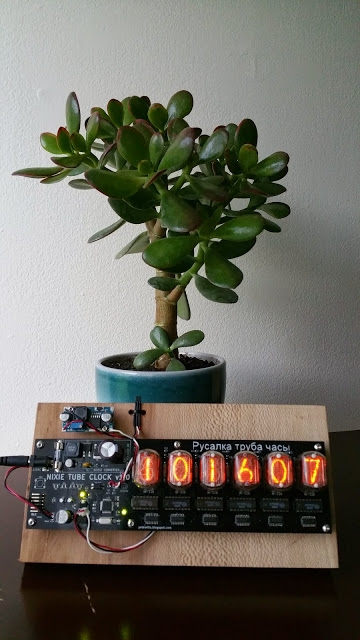
Prior to discovering the pullup/pulldown mix up on the DS18B20, I had discovered that my linear voltage regulator supplying VCC was overheating. I had underestimated how much current the HV driver IC’s would consume – they doubled the circuit total. I also underestimated the voltage that would be coming out of my 12 V AC adapter. It is approaching 18 V DC after rectification.
To salvage this embarrassingly obvious oversight I ordered 10 premade buck converters from ebay for about $10 total. They are based on the LM2596 IC and are voltage output adjustable. Now, I feed that ~18 V DC into the buck converter and send ~6.5 V DC out to the linear regulator. Hopefully, I will remember this lesson and incorporate buck converters appropriately in the future.
Below are some pictures showing the repair/mistake. Since this photo was taken I have potted the linear regulator and wires to prevent shorts or strain failures.