Our goal for this project was to build an OBD-II compliant device that would communicate with any OBD-II enabled car and read back real time data as well as perform basic performance testing and diagnostics.
If you’ve ever had to take your car into the shop because of the dreaded “Check Engine” light, you can have the same appreciation for this project as we did. Since 1996, all cars sold in the United States have been required to implement the On-board diagnostics (OBD-II) standard. This standard allows mechanics and repair technicians to communicate with a vehicle’s on-board computer and read out data from it, including why the check engine light is on. Commercial OBD-II readers are available but offer limited functionality and are often expensive. Plus they are not nearly as cool as the project we decided to build.
High Level Design
We began our project based around a chip that is designed to handle OBD-II interpretation, the ELM327 from ELM Electronics. This chip has the capability to transmit in any of the various transmission standards implemented by different car manufactures, and was the basis for the hardware design of our project. It converts the different vehicle communications formats into ASCII strings that are transmitted using RS232 serial. Many custom OBD-II projects exist on the web and we pulled ideas from these designs, which are listed in our references section. For the most part though, our hardware design was based off of directions contained within the ELM327 datasheet and the other various components that we purchased such as the MCP2551 (CAN Transceiver) and our 4-line HD44780 compliant LCD screen.
We used menu structure ideas from our security system lab as the basis for some of our software, as well as how to implement the UART communications between the microcontroller and the ELM327.
A high level drawing of how each different device was connected in our project is shown below. This shows how the MCU communicates with the various components needed to implement the OBD-II standard. The transmission arrows from the ELM327 for the SAE and ISO standard communications indicate transmission and receiving hardware for both, since they do not operate at 5V like the ELM327.
In regard to legal issues surrounding this project, we don’t believe that we have breeched any legal boundaries in the creation or use of our project. Our LCD driver code falls under open source rules and the rest of the code is our own creation. If we were to attempt to produce this device commercially, we may be required to pay for our use of the SAE and ISO standards that we have implemented. Since we are not creating this device for commercial sale, our use of SAE and ISO standards information as provided by Wikipedia falls under fair use.
Hardware/Software Tradeoffs
One of the major design decisions in this lab was to use the ELM327 to communicate with the vehicle. It is certainly possible, and has been done before, to use a microcontroller to implement OBD-II communications with a specific brand of car. This is because although the OBD-II is a standard implemented in all cars sold in the US today, each car company has implemented it differently as described below, resulting in five distinct signaling protocols. Because of this, had we chose to implement all of the signaling and modulation in software, we would only have had time to implement one specific signaling protocol which would only work on certain types of cars. Because we wanted to be able to interface with many different types of cars, we chose to use the ELM327.
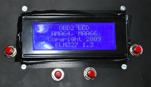
When deciding on a user interface we knew that we would require user input from buttons as was implemented in our final design. We also wanted to use an HD 44780 compliant LCD like the one’s used in lab. Since we wanted to display more information and make it easily readable in a dark car, we chose a nice blue backlit 4 line HD 44780 compliant LCD found on Ebay.
Standards
There were by definition many standards we needed to abide by for our project to work correctly. The first, and most obvious, is the OBD-II standard. It has been required on cars sold in the US since 1996. One of the primary specifications of OBD-II is the connector: a 16-pin (2×8) SAE J1962 connector. A universal female side is provided on the car, usually under the steering wheel on the driver’s side. It also specifies a standard set of diagnostic trouble codes (DTC’s) that allow mechanics to identify problems with the vehicle, as when the “Check Engine” light comes on.
The signaling protocols are important to be aware of, even though we did not have to implement each one individually in our design. SAE J1850 defines the standard protocol used by most American car manufacturers. Ford Motor Company uses a variation on the J1850 protocol with pulsed width modulation and a +5V high voltage on the communication lines. General Motors uses a variation on the J1850 protocol with a variable pulsed width format and a +7V high voltage on the communication lines.
There are three ISO standard signaling protocols: ISO 9141-2, ISO 14230 KWP2000, and ISO 15765 CAN. ISO 9141-2 is very similar to RS-232 but it uses the battery voltage (12V) as a signal high voltage and is used primarily in Chryslers, European, and Asian vehicles. ISO 14230 KWP2000 is almost identical to ISO 9141-2 but with larger message lengths. Finally, the ISO 15765 CAN (Controller Area Network) protocol has been phased in as the only signaling protocol on cars sold the US, beginning in 2008.
Hardware Design
Because of the nature of this project there was a significant hardware component to the design. The major hardware components as shown above in the high level design are: the ELM327, the ISO/SAE/CAN transceiver hardware, the MCU and target board, the LCD screen, and the buttons. Early on we made the design decision that it would be most convenient to use this device if it were completely battery free, powered completely through the OBD-II port which draws 12V from the car’s electrical system. This was consistent with the goal of our design, which was to make an easy to use OBD-II reader that is typically used in garages and not necessarily in close proximity to an outlet.
Voltage Regulation
To properly divide up the different hardware portions of this design requires an understanding of what each portion does and what kind of signals and voltages it will carry. The microcontroller target board is an all digital board with all voltages levels existing between 0 and 5V. The decision was made early on to leave the voltage regulator on this board and regulate the car’s 12V to 5V on the target board using the on-board regulator provided (LMV340LAZ). The ELM327 is similar in function to the microcontroller in that it operates primarily in a digital 5V signals because it is a microcontroller itself. The MCP2551 CAN transceiver is also an all digital device. These two IC’s along with indicator LEDs and a 4MHz crystal for the ELM327 were placed close together on one board that we referred to as the “digital board”.
The analog board contained much of the transmission and receiving hardware necessary for implementing the SAE and ISO protocols, as well as voltage regulation. Unlike the 5V digital board, this “analog board” contains 12V, 5V, and 6V voltage levels on one board. A 78L05 12V-5V regulator provides the 5V source for the digital board as well as part of the SAE interface. The SAE interface also requires a 6V source, which is provided by a 317L regulator. The ISO interface operates at the battery voltage and so the 12V from the car is used to drive the transistors for ISO communication which is also found on this board. The 12V is not connected anywhere near the ELM327 on the digital board in an attempt to isolate it as much as possible from the 12V that can (and once during this project did) destroy the ELM327.
ELM327
The ELM327 is really a specially programmed microcontroller PIC designed to handle communications in the OBD-II standard. It operates on the 5V rail provided on the digital board and provides debugging feedback via 4 LEDs that indicate Tx and Rx lines to the car and RS232 Tx and Rx. It operates at a frequency of 4MHz as provided by an attached crystal.
Data is received through one of the three signaling standards and then by the ELM327 which interprets the data and transmits it on a standard RS232 line that can be read by the ATMega644. Similarly, when a command is sent to the ELM327 by the MCU, it is interpreted and converted into the correct signaling protocol which is then transmitted to the car. The ELM327 does not actually read the commands or data that is being sent but simply converts ASCII data on the RS232 line to the proper voltages at the OBD-II port.
The transmission hardware is used to convert the signal output from the ELM327 into the proper voltages for the car. Since the SAE protocol requires 5V or 7V depending on whether it is using PWM mode or VPW, both of these voltages are fed using transistor pairs (PNP and NPN) to the actual transmission line that connects to the OBD-II port. The 7V (closer to 6.5V in practice) is provided from the 317L regulator.
The ISO transmission hardware is a relatively basic design that converts the 5V level from the ELM327 to the 12V battery voltage by tying the ELM327 pins to the base of 2 NPN transistors in a common emitter configuration. Similarly, the CAN protocol is implemented within the MCP2551 which is connected with two lines to the ELM327.

A detailed schematic of how the ELM327, MCP2551, and transceiver hardware were connected is shown in the appendix. On the schematic is an optional RS232 interface that we chose not to implement since it was not required to for communications with the MCU. The one major problem we encountered with this portion of the project was a blown ELM327 due to a 12V source reaching the digital board. Bruce and the TAs were able to assist us in locating the source of the high voltage (a poorly soldered resistor which was “popped” out with a little extra force) and the issue was corrected.
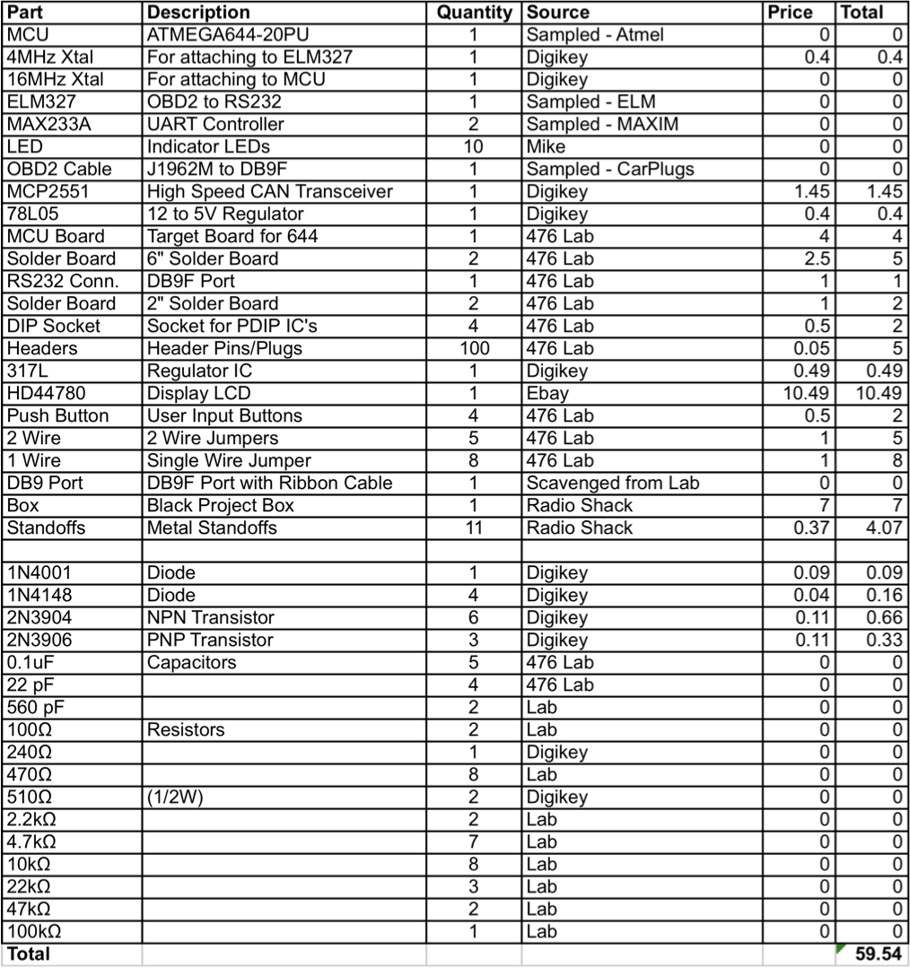
Parts List:
For more detail: ODB-II Automotive data interface using Atmega32