Introduction
Sensing in autonomous vehicles is a growing field due to a wide array of military and reconnaissance applications. The Adaptive Communications and Signals Processing Group (ACSP) research group at Cornell specializes in studying various aspects of autonomous vehicle control. Previously, ACSP has examined video sensing for autonomous control. Our goal is to build on their previous research to incorporate audio source tracking for autonomous control.
Our project involves implementing a signal processing system for audio sensing and manipulation for the control of an autonomous vehicle. We are working with the ACSP to develop PeanutBot to help advance their research in audio sensor networks. Our system will have two modes, autonomous and control. In autonomous mode, the robot will detect and follow pulses of a predetermined set of frequencies and the robot will approach the source. In control mode, the robot will execute commands by an administrator on PC transmitted to the robot via an RS-232 serial connection.
A short video demonstration of the robot is available at YouTube for viewing, and for download in AVI (29 MB), XVid 4 (5 MB) and Windows Media Video (6 MB).
High Level Design
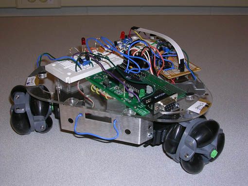
The PeanutBot robot consists of three microphone circuits, three servo motors, an MCU and a PC. The PC is used to communicate with the MCU in control mode for transmitting commands. During development, the PC communication was useful for testing, debugging and verification.
The three microphones were used to triangulate the angle of the source relative to the robot. The audio source plays a continuous stream of pulses. Pulses were chosen over a continuous tone because, instead of detecting phase difference in the audio signal, our system detects the arrival time of the signal at a certain amplitude at each microphone. The robot is designed to be autonomous and is, therefore, not synchronized with the pulse generator. As a result, the time of flight of each impulse is not available and the robot is unable to quantify the distance to the source. Instead, the robot advances by a small predetermined distance and listens for the signal again. To find the sound source, the robot listens for the arrival of an impulse on any of the three microphones. Once an impulse has been detected at one of the microphones, the robot records the microphone data at 10 microsecond intervals for 10 milliseconds. Using this data, the arrival time of the impulse at e! ach microphone is calculated and the direction of the source is obtained. Once the angle of the source has been identified, the robot rotates and pursues the source for a short period, and then promptly resumes triangulation of the signal to repeat the process.
Background Mathematics
The three microphones are placed at equal distances (7 inches apart) and one microphone is chosen as the first microphone. To find the location of the sound source, the difference in the arrival time of the signal at the microphones is calculated according to the equations shown below.
To calculate the angle of the source with respect to the front of the car, a lookup table containing arrival times and angles is used. The arrival times in the lookup table are calculated using the speed of sound at Ithaca’s altitude (343.966 m/s) and the distance between microphone one and the other microphones on the plane of the sound wave fronts for each angle in the table. This table maps the time differences t1 and t2 to a specific angle with an accuracy of 1 degree. Once the arrival times are observed, an angle is chosen based on the closeness of the relative arrival times to t1 and t2.
Logical Structure
PeanutBot has three software state machines for the servo control, user control mode, and autonomous control mode. The robot boots up in autonomous mode but can be transferred into user controlled mode if given instructions via its serial port. The control mode that is selected operates on its data, updates the appropriate servo variables, and transfers control over to the servo control state machine. The servo state machine will read and operate on the servo control variables and, once finished, return control to the mode which called it.
Hardware / Software Tradeoffs
During the design of the robot, there were hardware and software tradeoffs. Most notably, interfacing with the microphones had a complicated circuit to parse information before the software on the MCU manipulated the data. While the MCU does have an 8-channel A/D converter which is significantly more than the 3-channels required for triangulation, the on-board A/D converter requires several hundred microseconds to converge for a single channel, and only 1 channel can be read at a time. As a result, reading all three microphones on the MCU would require about 1-2 ms. Since the microphones were positioned 7 inches apart, it would take less time for the sound wave to travel from the first microphone to the second microphone then for the first A/D reading to converge. Furthermore, reading the microphones in serial instead of parallel would create an inherent delay added asymmetrically to the microphones, making it difficult to triangulate the source of the microphone. Con! sequently, most of the manipulation of the microphones was done in hardware to maintain the functionality of the robot.
Standards
The design of the robot conforms to IEEE standards such as the RS232 standard protocol.
Hardware Design
The hardware design consists of three microphone circuits, a microcontroller, a robot frame, three servo motors, three omni-directional wheels, a 9V battery for the MCU and circuitry, and a AA-battery pack for the servos. Each microphone circuit consists of amplifiers, filters, and comparators. A diagram of the Hardware and software is shown below i
Microphone Circuitry

To control the level of the microphone output, resistors are used to center the signal around 1.5V. This level-shifted output is amplified via an operational amplifier and then passed through a passive lowpass filter. It is then put through a half-wave rectifier with a capacitor to bridge the gaps between positive swings caused by the half-wave rectifier. That output is then passed though an analog comparator to discretize the signal for reading into the port pin on the MCU. The discrete output of the microphone circuit is approximately 4V when sound is detected and 0V when no sound is detected. All 3 microphone circuit outputs are read in parallel using PORTA on the microcontroller. The output is also passed through an LED circuit to ground in order to debug when a particular microphone circuit detects sound.
Parts List:
| Acronome PPRK Robot Vehicle | $325 |
| Batteries (9V and 4 AA) | $10 |
| Audio Source (Speaker) | $0 |
| Atmel Mega32 Microcontroller | $8 |
| Custom Solder Board | $1 |
| White Breadboard | $4 |
| Max233 CPP | Sampled |
| RS232 Connector | $8 |
| Analog Circuit Components | $0 |
| Green Tubing | $5 |
| Total | $361 |
For more detail: PeanutBot, The Audio Homing Robot Using Atmega32