Introduction
We designed a device that measures and graphs various aspects of AC power and acts as a computer-controlled remote switch.
With the recent push for green energy and environmental friendliness, more and more people are concerned about their personal daily power usage. We developed a microcontroller-based device to measure AC power. The user will be able to insert the device between the wall socket and the device under test (DUT) to measure the amount of AC power being used. With this device, environmentally conscious people can use the C# application that we developed to monitor their energy usage with real time graphs and data display.
Our device calculates and reports the following parameters in real time:
- Real power
- Apparent power
- Power factor
- RMS Voltage
- RMS Current
- Frequency
- Energy usage (Kilowatt-Hours)
In addition to measurements, our device also has a remote switch that allows the computer to turn the power on or off and set wattage limits for auto shutdown.
DISCLAIMER: AC POWER CAN BE EXTREMELY DANGEROUS UNLESS YOU KNOW WHAT YOU ARE DOING. PLEASE CONSULT A PROFESSIONAL AND REFER TO THE SAFETY SECTION FOR MORE INFORMATION.
High Level Design
Rationale
The primary inspiration for our project was the EnerJar, developed by Matt Meshulam and Zach Dwiel at Washington University in St. Louis. The Kill A Watt is a similar commercially available product. We improved upon the EnerJar by making it safer and simplifying the design significantly. The EnerJar is not optically isolated and therefore is potentially very dangerous. We extended upon the Kill A Watt by developing a computer interface to provide real time graphs and remote switching.
Background Math
In an AC circuit voltage, current, and power are defined as the following:
![]()
![]()
![]()
When the load is purely resistive, voltage and current are in phase. When the load is either inductive or capacitive, voltage and current are out of phase.
Using several trigonometric identities, the power can be expressed as:
![]()
The average (real) power, P. Real power is the energy that flows to the load. It is what the electric company bills home users for. It can then be written as:
![]()
Reactive power, Q, is the energy that flows back and forth in an inductive or capacitive load. On average, no reactive power is consumed. It can be written as:
![]()
Together, real power and reactive power form complex power. This is the actual power that the electric company is supplying. It can be written as:
![]()
The magnitude of complex power is called apparent power, |S|, in units Volts-Ampere.
The power factor, PF, a measure of efficiency. It is defined as:
![]()
Logical Structure
The block diagram is shown in Figure 1. Our device sits between the mains line and the device under test. Current measurements occur on the neutral line. The relay is switched on the AC live line. A voltage divider is used to step down the voltage to the correct levels. All signals are optically isolated before reaching the MCU
Hardware / Software Tradeoffs
Hardware was used to bring voltage levels into the appropriate range for the Mega32 internal ADC. In software, the Mega32 was used to sample the voltage levels at a frequency of 1 KHz and perform the appropriate calculations in real time. The software also handles interacting with the computer and controlling the relay switch.
The Mega32 ADC channels are multiplexed and not simultaneous. An external simultaneous ADC chip could have been used to sample current and voltage at the same time, resulting in slightly more accuracy. However, to save costs, the extra hardware was not used. The internal Mega32 ADC was switched in software to take one sample after the other. This was deemed good enough for our purposes.
Fixed point (20:12) was used instead of floating point to speed up multiplication and division operations. The Mega32 hardware performed floating point multiplication operations much slower than integer multiplication operations. Therefore, some accuracy was traded for speed.
Standards
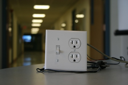
The sockets used in most American homes adhere to the NEMA 5-15 standard, set by the National Electrical Manufacturers Association. It is rated for 15 A / 125 V at 60 Hz.
The left wider flat blade is neutral, and the right flat blade is AC live. Neutral is the zero voltage reference point. The voltage on the live contact is measured with respect to the neutral contact. AC live oscillates between roughly +/- 170 V about that point. The circular hole is earth ground. It is used as a safety mechanism for device with metal casings, so that it does not produce a dangerous electric shock when people touch the case.
The standard IEC connector defined by International Electrotechnical Commission specification IEC 60320 is commonly used to connect mains AC power to devices such as computer. One of these was salvage for use in our project. The one we used was a 3-conductor standard rated at 16 A.
Patents, Copyrights, and Trademarks
There are quite a few commercially available professional AC power measurement devices on the market. Kill A Watt is a registered trademark. The name PowerBox does not knowingly infringe on any trademarks. The design of our project does not knowingly infringe on any patents.
Hardware Design
Voltage Measurement
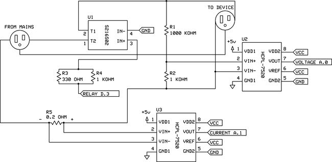
To measure voltage, the general idea is to use a very large voltage divider to divide the 170 V peak-to-peak signal down to level which can be sampled by the ADC. Using a 1001:1 voltage divider (with 1 MΩ and 1 kΩ), as shown in the Appendix B schematic, 170 V peak-to-peak is divided down to 0.17 V peak-to-peak. A very large resistor (1 MΩ) was used in the divider to limit the current between AC live and neutral. Assuming a 170 V drop, only 0.17 mA flows through the 1 MΩ resistor, dissipating 0.03 W, well within the power ratings of the resistor. To calculate the line voltage from the voltage divider output, the following equation can be used:
![]() (Eq. 1)
(Eq. 1)
Current Measurement
To measure current, the general idea is to break the neutral line and insert a very small current-sensing resistor (0.2 Ω). This would create a small voltage difference across the resistor. Since we know the voltage drop and the resistor value, we can mathematically determine the current through the neutral line. Since the resistance is very small, very little power is dissipated through it. We carefully checked the ratings of this and other circuit components for power ratings. The resistor is rated for 3 W. We expected a 200 W computer to draw about 1.7 A. This results in a voltage drop of 0.34 V and a power dissipation of 0.58 W. To calculate the line current from the current-sensing resistor voltage drop, the following equation can be used:
![]() (Eq. 2)
(Eq. 2)
Isolation, Amplification, and Offset
In our first design iteration, we referenced the EnerJar design. We wanted to use an opamp bias the AC signal by 2.5 V in order to make the signal positive. The signal was to be put through a precision amplifier to convert it into the proper range for the ADC. This scheme would require that all of the grounds of each circuit element to be connected, which was deemed very dangerous. Therefore, after some analysis, it was rejected for safety reasons.
In our second design iteration, we added optoisolators to completely isolate the dangerous high voltage circuit from the MCU. Since the optoisolators stocked in lab were by nature digital devices, we wanted to use a PWM chip to convert the analog signal into pulses to send across the optoisolator. We also wanted to use precision amplifiers to convert the signal into the correct range. This would have been a workable solution, but we wanted to find a more efficient method that required fewer ICs.
In our third design iteration, a breakthrough occurred when we found the Avago Technologies HCPL-7520 linear optoisolator. This device has a linear transfer characteristics curve for input range -256 mV to 256 mV. The input is differential and the output is scaled to Vref. The gain is Vref / 0.512. This single chip allows us to bias the signal to Vref / 2, amplify it, and isolate it. It results in a solution that is simpler and cheaper to manufacture. The HCPL-7520 was used for both voltage and current measurements. Vref was set to Vcc (5 V) of the MCU. To calculate the input voltage of the HCPL-7520 from the output voltage, the following equation can be used:
 (Eq. 3)
Combining the voltage divider (Eq. 1) and current-sensing (Eq. 2) equations with (Eq. 3), we get:
 (Eq. 4)
 (Eq. 5)
The voltage output was connected to Port A.0 of the MCU. The current output was connected to Port A.1.
Power Switching
To do remote power switching, the Sharp S216S02 solid state relay was used. This relay is optically isolated and rated for 240 VAC and 16 A. We used this relay to switch the AC live line. A 330 Ω and a 1 kΩ resistor were placed in parallel (248 Ω series resistance) to limit the current of the light emitting diode in the relay. Port D.3 of the MCU was used as the output to control the relay.
Supply
On the high voltage side, the optoisolators were powered using a salvaged 12 V AC-DC unregulated power supply. We regulated it down to 5 V with a regulator. On the low voltage side, the optoisolators were powered using Vdd and Gnd of the MCU.
Physical Design
For physical design, a solder board was used to place our circuit. The left side of the board contained dangerous high voltage elements. The right side contained MCU inputs. The 2 sides were completely isolated. Cables from inside the IEC connector were used to connect AC lines. The IEC connector head was used to connect our device to the wall. Devices under test were connected via a wall socket. A salvaged serial cable was soldered to the port instead of an RS232 connector. Everything was contained inside a plastic wall box for safety. Please consult the Safety Section for how our device was isolated.
Parts List:
|
Item
|
Unit Price
|
Quantity
|
Price
|
| Ohmite 13FR200E current sense resistor |
$1.72
|
1
|
$1.72
|
| Avago Technologies HCPL-7520 linear optoisolator |
$3.83
|
2
|
$7.66
|
| Sharp S216S02 solid state relay |
$5.83
|
1
|
$5.83
|
| Atmel Mega32 |
$8.00
|
1
|
$8.00
|
| Custom PC board |
$5.00
|
1
|
$5.00
|
| Power supply |
$5.00
|
1
|
$5.00
|
| Power supply |
Salvaged
|
1
|
Salvaged
|
| Solder board |
$2.50
|
1
|
$2.50
|
| RS232 serial cable |
Salvaged
|
1
|
Salvaged
|
| Max233CPP |
Sampled
|
1
|
Sampled
|
| IEC power connector |
Salvaged
|
1
|
Salvaged
|
| NEMA 5-15 power socket, switch, and wall box |
$9.99
|
1
|
$9.99
|
| Total: |
$45.70
|
||
For more detail: PowerBox: The Safe AC Power Meter