Introduction
The Newest Innovation in Patient Compliance
The Portable Programmable Medication Scheduler (PPMS) is a modern solution to the century old problem of patient compliance, featuring four medication bins, audio/visual alarms, a graphic LCD, and serial communication with a Java Swing PC GUI.
The conjunction of Electrical Engineering and the practice of Medicine has grown increasingly significant over the course of the past few decades, producing ever more innovative devices for the benefit of human healthcare. While biometric devices are often showcased in this arena, control devices such as ours are playing an increasingly substantial role as supplementary and autonomous caregivers. Providing a programmable medication scheduler forms an ever-present link between doctor and patient, capable of avoiding many common mishaps related to patient compliance.
High-Level Design
Patient failure to adhere to medication protocols is an often overlooked yet tremendously signicant problem in medicine. Such compliance failures, due to forgetfulness or lack of information, result in missing dosages or taking medication incorrectly. Obviously, protocol mistakes like these have dangerous and potentially fatal consequences. A device capable of reminding patients which medication to take and when to take it could decrease the needlessly high rate of fatality due to non-compliance.
User Interface
The user perspective of the PPMS is intentionally simple, developed entirely with a target base of elderly and aging customers in mind. All scheduling complexity is hidden from the patient via the programmable serial interface maintained by a physician, family member, or perhaps the customer himself in some cases. The patient interacts only with two large push buttons and four pill bins, not unlike those used to manually manage medication. Under normal operating conditions, once the physician or other responsible person uploads a medication protocol the device becomes entirely autonomous until a schedule change is needed. Dosage reminders are announced by sounding an alarm and turning on an indicator light above the appropriate medication bin. At this point the patient has the option of ‘snoozing’ the reminder for 5 minutes or opening the bin. While announcing the reminder, the medications contained by the bin are displayed by name, dosage amount, color and size on the screen (along with any additional neccessary information). The displayed information may be cycled through the use of either pushbutton. Once the corresponding bin is closed again the patient is ask whether he or she took the prescribed dosages. If not, a reminder announces the bin again in five minutes, otherwise an acknowledgement is displayed and the device returns to normal operation awaiting the next reminder time.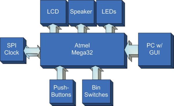
From the doctor’s viewpoint, the PPMS is a simple computer peripheral capable of ensuring the proper scheduling of a patient’s medication. The scheduling process takes place over a serial connection between the device and a PC. The programmer need only launch the scheduler application to begin interfacing. Medications are read in from a text library to avoid mispellings and redundant information. Each medication may be assigned to a particular bin with a certain time and amount, an interface entirely analogous to the device itself. Once the data entry is complete, clicking the download button will send the schedule to the device and immediately verify its integrity, informing the user of the encountered results. After a successful download the device is ready for normal autonomous operation.
Hardware Structure Overview
We wanted the ability to display images as well as text to our users, so we opted for a graphical LCD, despite the added complexity. For screen size, we felt that 128×64 pixel resolution was suitable for the amount of texts and graphics we wished to display. A smaller screen could have been used, but at that point text would likely get hard to read.
One major limiting factor was that we opted to use a monochrome LCD rather than a color LCD. This decision was made based on our own lack of experience with programming LCDs in general, and because we were primarily using the LCD for text, and could still give medication color information in the form of text.
The next and more important decision with regards to LCD was selecting the LCD controller itself. The KS0108 controller by Samsung seemed very prevalent with LCDs of this screen resolution, and the documentation made it seem like a simple controller to interface with. Its instruction set was small, and it had no on-chip character generator, or multi-layered graphics capabilities. However, we also had no need for either missing feature as we planned to use large fonts and only simple bitmaps for graphics.
The major downside to this controller was that the documentation was occasionally ambiguous, and unofficial sources on using the KS0108 often conflicted with each other.
In addition to the LCD, we also opted to use an external real-time clock (RTC) for our device. As our scheduler is based entirely off a 24 hour clock, and we planned for our device to have its batteries changed more often than it was programmed, it was important that we retained an accurate clock through power outages to the main device. The solution was a RTC package that could be powered through a 3V coin battery, with a much longer battery life expectancy.
We opted to use SPI as the form of communication between microcontroller and RTC because a SPI send/receive function already existed in CodeVision AVR, which would save us time on coding. Unfortunately, the RTC models that used SPI communication had a great deal of functionality that we did not need to make use of, including interrupt generation, reset generation, the ability to set alarms, and tracking of time up to centuries. This added complexity ended up causing unnecessary complications during implementation. A simpler device would have probably been easier to work with. Also, SPI communication on the Mega32 is handled on the same pins as the programming pins this again added complexity to our implementation as we had to protect our microcontroller from being programmed incorrectly.
Software Structure Overview
Software design for the device relied heavily on hardware constraints and abilities. Modularity kept code complexity to a minimum and allowed individuals to work independently. Thus the architecture features four components, the main scheduler code, the LCD library, the RTC library, and the Serial Interface library. Each component faced its own relevant tradeoffs but are designed to work together seemlessly despite any internal difficulties.
LCD and RTC libraries mainly focus on hardware-software interaction and therefore serve essentially as drivers for the use of the main scheduler. Their complexity is discussed more thoroughly in the hardware section.
Initial software decisions involved the development of a serial medication protocol which could easily transmit non-redundant, compressed schedule information between a PC and the device. A bare minimum number of transmissions are used in transfer schedules. This protocol is outlined below.
The most cumbersome software decision and implementation involved non-volatile memory management. In order to preserve a patient’s schedule between power losses the EEPROM was chosen to store vital schedule information. However, the size of this memory resource is very limiting and required strict compression of schedule information. Likewise, EEPROM interaction is sparsely documented are required quite a bit of guess work managing pointers, reads, and writes.
Our main scheduler file required the greatest degree of tweaking to ensure potential customer satisfaction with the interface. The device is specifically design to act in ways one would expect with no particular or surprising behavior at any point. Prompts and displays required a high degree of readability not to mention intelligible wording for any event. Much thought and consideration comprises the current interfaces which do indeed work to our expectations.
Worth Noting
Products and patents similar to our prototype do exist. The company VRI has a medical alarm pill dispenser, which is designed as a large base station, and appears to only have a digital clock readout for a display. We have also found patent no. 5,347,453 (filed in 1994) which describes a programmable and compact integrated alarm and medication information display that would attach to pill containers or eye-drop dispensers, and display information regarding doses and special instructions. However, judging from the drawing, the display of the device is quite small (about the size of a medication label), and is made to attach to existing medication containers. We feel our proposed device would be a considerable improvement over these products.
Two standards are relevant to the device, SPI and USART communication for real time clock and PC interaction respectively. We also anticipate displaying time in the accepted fashion of HH:MM:SS. While this is beyond the scope of our project, it is worth mentioning that information entered into the patient mediation interface should conform to standards and information provided by the American Society of Health-System Pharmacists’ Drug Information book, which includes information on label and off-label use for drugs, as well as drug interactions.
Hardware Design
Pin Connections
|
LCD Operation
Power
The LCD has 4 power connections: GND, +5V, -10V, and an adjustable voltage Vo for contrast adjust. The -10V power connection presented a problem for us because we only 0 and +5V to work with for power, and the LCD needed a relatively large voltage to display with good contrast. We solved this problem with a DC-DC converter from All Electronics, set up as shown below.
Originally we did not have the 4.7k load resistor in place, and found that the converter was drawing in excess of 200 mA of current. Adding the resistor reduce this to a much more acceptable 10-16 mA, which was within our power budget.
Parts List:
| Vendor | Part | Cost($) |
| Custom PC Board | 5.00 | |
| Atmel Mega32 | 8.00 | |
| Maxim-IC | Max233CPP | sampled |
| 6″ Solder Board | 2.50 | |
| Digikey | Pushbuttons | 2 x 0.94 |
| All Electronics | Mini Snap Action Switches | 4 x 1.00 |
| Digikey | STMicroelectronics M41T94 | 4.13 |
| All Electronics | DC-DC Converter | 0.50 |
| LCD – AGM1264F | 9.95 | |
| Digikey | 32.768 kHz Crystal | 0.28 |
| Digikey | 9V Battery Holder | 1.77 |
| Digikey | 9V Battery | 2.00 |
| Digikey | 3V Coin Battery Holder | 1.55 |
| Digikey | 3V Lithium Battery | 0.35 |
| Total | $41.91 | |
For more detail: Programmable medication scheduler