Introduction
Power supplies are perhaps the most crucial elements of a battery-powered system. Knowledge of some basic regulator topologies will help you select and design the right supply configurations for your needs. This tutorial presents an overview of regulator topologies for battery-powered equipment. The discussion covers linear regulators, charge pumps, buck and boost regulators, inverters, and flyback designs. The importance of peak current is explained, and schematics of each topology are shown.
Regulator Topology Overview
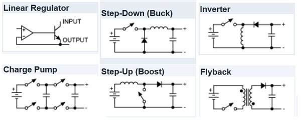
Desktop computers, laptops, netbooks, smartphones, PDAs, and many other consumer electronic devices usually require more than one power supply. These devices may need an AC/DC adapter, a battery charger, a high-voltage DC/AC converter for the backlight, and other supplies for lasers, cellular radio transmitters, and auxiliaries. Table 1 shows the seven most common regulator topologies beginning with the simplest (the linear regulator) and progressing to more specialized types (like the flyback regulator). The table also lists the pros and cons of each topology.
Swapping components in a basic switching-regulator layout alters the circuit topology to create regulators that step up (boost), step down (buck), or invert an input voltage. Substituting a transformer for the inductor produces at least two more regulator circuits or auxiliary output voltages.
Table 1 omits complex topologies like resonant-mode regulators, because their control circuitry consumes too much power for small battery-operated systems. The rule for these systems is simplicity: the simpler the circuit, the better. Simple circuits have no magnetics, simple inductors, or 1:1 transformers. Off-the-shelf magnetics simplify assembly and minimize costs. Other topologies can be derived from the basic topologies in Table 1. This includes the Cuk converter, which combines the buck and boost topologies, and the forward converter, which combines a buck converter with half of a push-pull converter. However, these topologies are not discussed in detail in this tutorial.
Linear Regulators
Linear regulators are the simplest and least expensive of the power-supply circuits, but this ease of use generally comes at a cost. As indicated in Table 1, a linear regulator includes a feedback network that monitors the output voltage and adjusts it by controlling an internal pass transistor (BJT or FET). When the input voltage greatly exceeds the output voltage, this pass transistor dissipates large amounts of energy (in the form of heat) at high loads. This results in lower efficiency than a comparable switching regulator.
For more detail: Regulator Topologies for Battery-Powered Systems

