Introduction
In this project, we built a digital multi-meter utilizing near-field communication concept.
The system established a bidirectional wireless communication between the measurement unit and the base unit. The measurement unit is in charge of measurement and transmitting the result to the base, while the base is the user interface for measurement mode selection and output display. The two units are electrically and mechanically isolated. The intended communication range would be between 10 and 15cm.
The mechanical and electrical isolation improves the safety of measurement under some high voltage or high power situations, where direct electrical connection is dangerous.
High Level Design
1. Overview
The major goal of the project is to build a short distance transceiver with as simple circuitry and components as possible. Since we are not requiring a long distance communication (and we intentionally want to keep it short to avoid interference) or a high communication data rate, the design can be kept very simple and elegant, which is opposite to those commercial RF transceivers. We use a tuned LC tank as the antennas and the On-Off keying modulation scheme. The crude antenna and the modulation scheme turn out to work well since the signal to noise ratio is high due to the short communication range. We use the carrier frequency of 181.18 KHz, which is a legal band to use under certain constraints according to FCC. The data is organized in the form of serial package. ATMega644 is used to both process the received signal and to drive the antenna for transmission. Due to the budget and time constraint, the communication system is half-duplex. An op-amp is used to amplify the received signal before the MCU can process it. On the base unit, a LCD is used for output and two switches are included for user to select the measurement mode. The measurement unit has three independent probes (one for each type of measurement) and protection circuit for measurement purpose.
2. Logical Structure
(a) Hardware
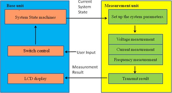
The hardware of this project has two main parts: the base unit which takes input from the user and controls the measurement unit, and the measurement unit which implements instruction of the user and send the measurement results back to the base unit. Both units have the circuit for near field wireless communication and a MCU for data processing. As a result, the two circuits would look similar. However, while the base unit has switches takes input from the user, the measurement unit includes circuits for measuring voltage, frequency and current as well as the circuit protection units. Below is a high level illustration of the hardware blocks.
(b) Software
The software part of the project consists of two main parts: the code for the base unit and the code for the measurement unit. The two units share some code and have others different. Below are the block diagrams of the software for both units:
The code for the RF system is divided into two parts: system level and infrastructure level. The infrastructure level conducts the operation of sending or receiving one byte, and the two units share the same infrastructure level code for RF system. The system level controls the timing between receiving and transmission, and this part is different in the two units.
The measurement part of code is similar to what we have done in lab2. The LCD update, update system state and the user input detection are rather straight forward parts.
3. Software Hardware Tradeoff
The first tradeoff we faced is that whether we should add some error checking mechanism in the communication protocol to be more noise-resistant. If there is an error checking embedded, it will be more demanding on the software but less emphasis on the hardware. The software has to do more complex processing on signal. In addition, the overhead of the error checking will decrease the effective data transmission rate, requiring more smart coordination between transmission and receive (due to the half-duplex nature of the system) to mitigate the effect. But we can accept a lower signal to noise ratio, putting less constraints on the hardware. As we will see later in the software design section, we embedded error checking mechanism for our control signal but not for the data signals to balance the tradeoff.
The second tradeoff is about if we should insert hardware processing between the antenna and the MCU. If the MCU is directly interfacing with the antenna, the software will do more processing on the received raw signal. If there is intermediate hardware doing pre-processing work, the MCU can free its computation power from the signal processing and do more computation-intense tasks (although the tasks in our project are not computation-intense). The other issue related to this tradeoff is the carrier frequency. Since our MCU is running at a frequency of 16 MHz, the theoretical upper bound for the carrier frequency is 16 MHz (the actual working upper bound is a lot lower) without the pre-processing by the hardware. This limits our choices of the communication bands as well as the rate of data transmission. With hardware pre-processing, we could go beyond the limit of 16 MHz, having more choices on the bands and higher data rate. In our specific situation here, the DMM does not require a high data transmission rate, nor does it have computation-intense tasks. In addition, we want to keep the hardware as simple as possible and heavily leverage the versatility of the MCU. Therefore we finally choose to make MCU directly interfacing with antenna.
4. Related Standards
Since our project involves RF transceiver, we have to abide by the regulations from Federal Communication Committee (FCC). The band we propose to use is 160KHz to 190KHz. This band is regulated by FCC 15.209, 15.213 and 15.217 for the following requirements, which we believe that our system meets:
- The total input power to the final radio frequency stage (exclusive of filament or heater power) shall not exceed one watt. Our antenna would consume very low power since they are small and close together.
- The total length of the transmission line, antenna, and ground lead (if used) shall not exceed 15 meters. Since we are going to use LC tank to build the antenna, the length of the antenna would be about 5.5*4*14*2=308cm which is much shorter than the maximum total length. The length of the other components will be even shorter.
- All emissions below 160 kHz or above 190 kHz shall be attenuated at least 20 dB below the level of the unmodulated carrier.
- the emissions from an intentional radiator shall not exceed the field strength levels specified in the following table:
Frequency (MHz)
Field strength (microvolts/meter)
Measurement distance (meters)
0.009–0.490
2400/F(kHz)
300
0.490–1.705
24000/F(kHz)
30
1.705–30.0
30
30
Table.1 FCC regulation
5. Intellectual Property and Copyright
In our final project, we reuse some codes from the Minimum Mass Wireless Coupler project from Dick Cappels’ project website page. We obtain the permission to use and modify the code from the author. We also use one of the antenna designs from the website in our project.
Hardware Design
The hardware of this project is composed of two parts, the base unit and measurement unit. We will first elaborate on the base unit which reads input from the user and controls the state of the measurement.
1. The Base Unit
The graphs below show the basic structure and the circuit diagram of the base unit.
The base unit circuit can be divided into four major parts: antenna, op-amp, MCU and LCD. Their functions are briefly illustrated in the diagram below.
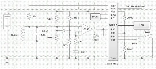
The antenna is composed of an LC tank with a 31.1 μH inductor and a two 2.2nF capacitors in parallel. The inductor is physically a 32 round 5.5cm rectangular copper coil. We chose this specific number of rounds because it is feasible and it will have reasonably large mutual inductance with the measurement unit inductor than a coil with fewer rounds. We chose this number after a number of steps. We first chose a number of rounds of 25. The value of the inductor is estimated from the formula L=k*N^2 where k is a constant and N is the number of the rounds of the coil. In the software design, we have chosen a frequency in the range of from 160k to 190 kHz to transmit signal. Therefore the values of the capacitors are chosen to make the resonance frequency of the LC tank around 180kHz. The resonance frequency is determined from a band pass circuit as shown below. W connected the left and right ends of the circuit to the function generator and the end from the LC tank to the oscilloscope. The output to the oscilloscope would be maximum around the resonance frequency.
Parts List:
| Part | Description | Quantity | Unit Price | Source |
| ATMega644 | MCU | 2 | 6 | Bruce Land |
| DIP socket | for MCU and op-amp | 4 | 0.5 | Bruce Land |
| LCD | Display unit | 1 | 8 | Bruce Land |
| Switch | two way switch | 2 | 0.5 | Bruce Land |
| Solder Board | 3 | 2.5 | Bruce Land | |
| Current Sensor | DigiKey #: 480-3254-ND | 1 | 18.16 | DigiKey |
| Header | Connection for LCD, target board | 75 | 0.05 | Bruce Land |
| Op-amp | LF353. Amplify received RF signal | 2 | 0.55 | Bruce Land |
| Target board | the interface for MCU | 2 | 4 | Bruce Land |
For more detail: Remote Controlled DMM With Minimum Mass Wireless Coupler Using Atmega644